Isuzu Amigo / Axiom / Trooper / Rodeo / VehiCross. Manual - part 1609


  Index      Isuzu     Isuzu Amigo / Axiom / Trooper / Rodeo / VehiCross - service repair manual 1999-2002 year


Search            


Content   ..  1607  1608  1609  1610   ..


Isuzu Amigo / Axiom / Trooper / Rodeo / VehiCross. Manual - part 1609


7C–12

CLUTCH

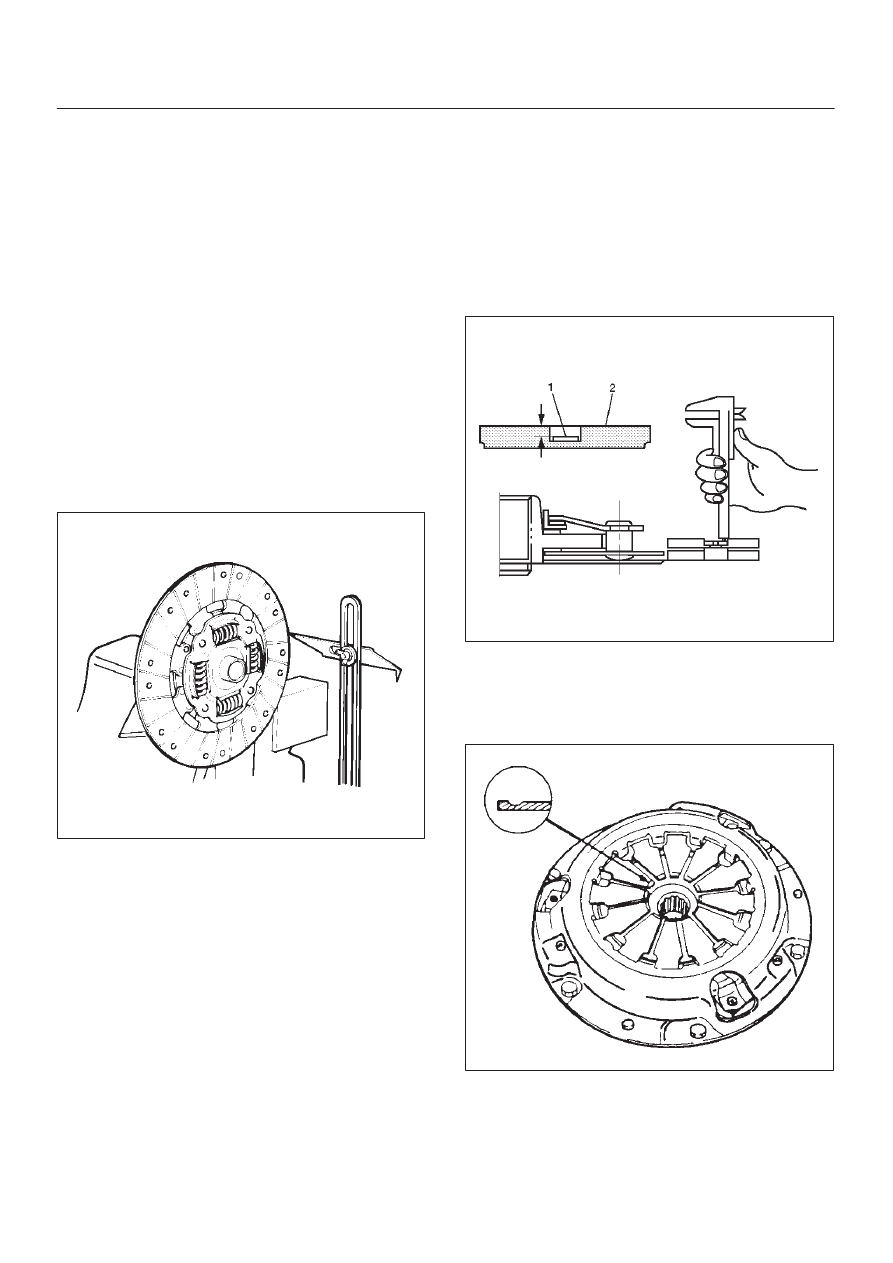
3. Slowly turn the driven plate.  Read the dial indicator as

you turn the driven plate.
If the measured value exceeds the specified limit, the
driven plate assembly must be replaced.

Driven Plate Warpage
Standard: 0.7 mm (0.028 in)
Limit: 1.0 mm (0.039 in)

Driven Plate Splined Hub Spline Wear

1. Clean the driven plate splined hub.
2. Install the driven plate to the transmission top gear

shaft spline.

3. Set a surface gauge to the driven plate outside

circumference.

4. Slowly turn the driven plate counterclockwise.

Measure the spline rotation play as you turn the
driven plate.

Driven Plate Splined Hub Spline Wear 
Standard: 0.5 mm (0.020 in)
Limit: 1.0 mm (0.039 in)

201RS009

Rivet Head Depression

Use a depth gauge or a straight edge with steel rule to
measure the rivet head depression (1) from the facing
surface (2).
Be sure to measure the rivet head depression on both
sides of the driven plate.  If the measured value is less
than the specified limit, the facing must be replaced.

Rivet Head Depression
Standard: MIN 1.3 mm (0.051 in)
Limit: 0.2 mm (0.008 in)

201RS010

Pressure Plate Assembly

Check the cover for cracks and distortion, and the
diaphragm spring for heat distortion, loosened rivets.
Check the diaphragm spring for wear.

201RS047

CLUTCH

7C–13

Installation

1. Clean and lubricate with grease.
2. Use installer J–1522 to install crankshaft bearing (6).

X22SE

015RS078

3. Apply molybdenum disulfide type grease to the areas

as shown in the figure and install shift fork (5).

F07RW030

4. Pack the inside recess (A) of the release bearing with

grease as shown in the figure.

201RY00004

5. Install driven plate assembly by using aligner

J–42877.

201RS049

7C–14

CLUTCH

6. Tighten the bolts holding the pressure plate assembly

(2) in the order shown in the figure.

Torque: 18N·m (13 lb ft)

201RS050

7. Remove the aligner.

NOTE: Do not strike the aligner with a hammer to remove
it.

8. Install transmission assembly (1) to the engine.  Refer

to Transmission Installation in Manual Transmission
section.

CLUTCH

7C–15

Clutch Assembly (6VD1)

Clutch Assembly (6VD1) and Associated Parts

201RS023

Legend

(1) Transmission Assembly
(2) Pressure Plate Assembly
(3) Driven Plate Assembly

(4) Release Bearing
(5) Shift Fork
(6) Fulcrum Bridge
(7) Flywheel Assembly and Crankshaft Bearing

Removal

1. Refer to “MANUAL TRANSMISSION” of Section 7B

for “REMOVAL AND INSTALLATION” procedure of
transmission assembly (1).


Content   ..  1607  1608  1609  1610   ..