Isuzu Amigo / Axiom / Trooper / Rodeo / VehiCross. Manual - part 1608


  Index      Isuzu     Isuzu Amigo / Axiom / Trooper / Rodeo / VehiCross - service repair manual 1999-2002 year


Search            


Content   ..  1606  1607  1608  1609   ..


Isuzu Amigo / Axiom / Trooper / Rodeo / VehiCross. Manual - part 1608


7C–8

CLUTCH

Clutch Assembly (Y22SE)

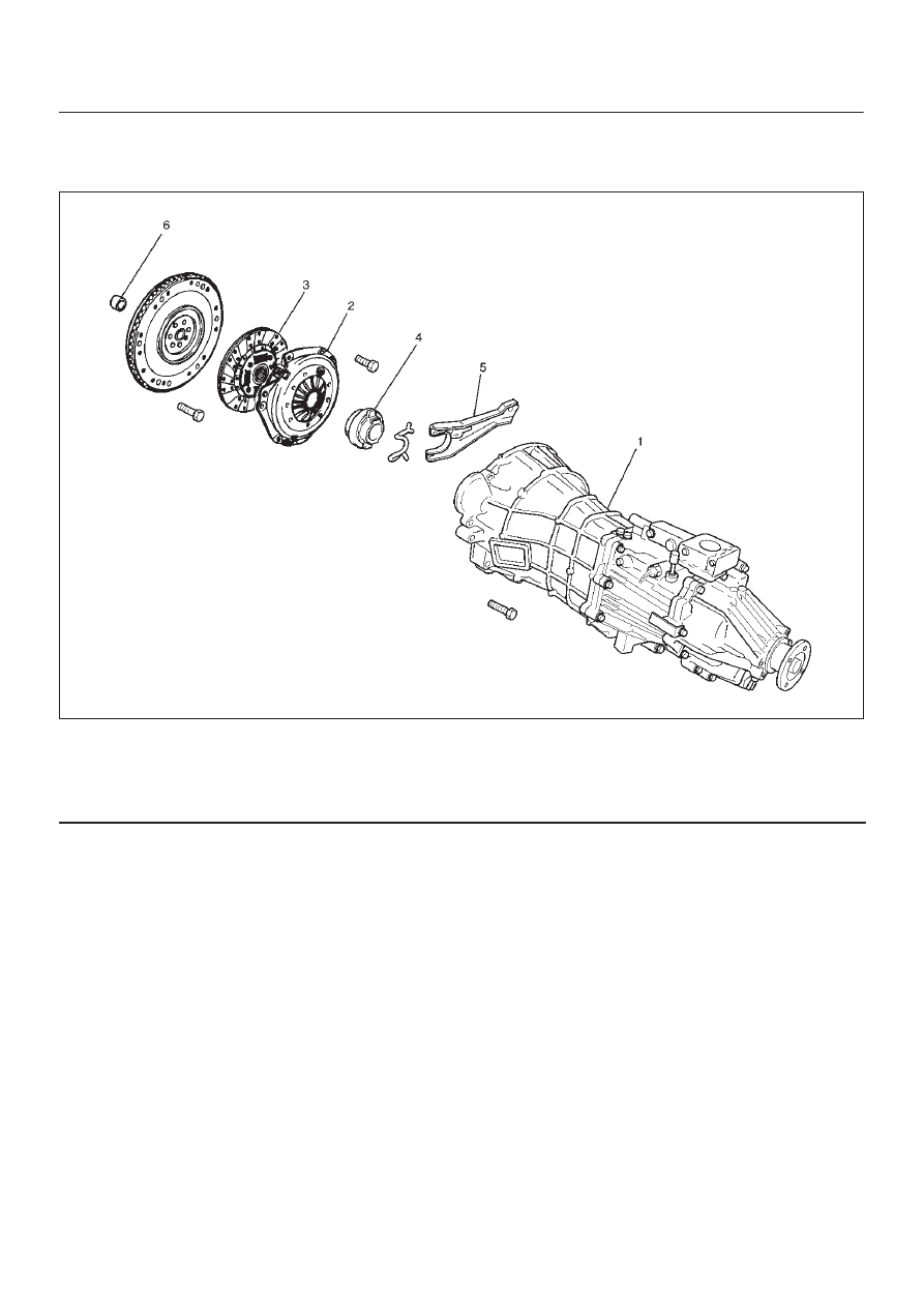
Clutch Assembly (Y22SE) and Associated Parts

201RX003

Legend

(1) Transmission Assembly
(2) Pressure Plate Assembly
(3) Driven Plate Assembly

(4) Release Bearing
(5) Shift Fork
(6) Crank Shaft Bearing

Removal

1. Remove transmission assembly, refer to “MANUAL

TRANSMISSION” of Section 7B for “REMOVAL AND
INSTALLATION” procedure.

CLUTCH

7C–9

2. Use the clutch pilot aligner (7) J–42877 to prevent the

driven plate assembly from falling free.

201RX002

Legend

(3) Driven Plate Assembly
(2) Pressure Plate Assembly
(7) Pilot Aligner

3. Mark the flywheel, clutch cover and pressure plate (2)

lug for alignment when installing.

4. Loosen the clutch cover bolts in the numerical order

shown in the illustration.

201RS036

5. Remove pressure plate assembly (2) and driven plate

assembly (3).

6. Remove release bearing (4).

NOTE: The release bearing is permanently packed with
lubricant and should not be soaked in cleaning solvent, as
this will dissolve the lubricant.

7. Remove shift fork.

D

Do not remove crank shaft bearing (6) except for
replacement.
Remove the crank shaft bearing (6) using remover
J–5822 and sliding hammer J–23907.

015RS077

Inspection and Repair

Make necessary adjustments, repairs, and part
replacements if wear, damage, or other problems are
discovered during inspection.

Pressure Plate Assembly

Visually inspect the pressure plate friction surface for
excessive wear and heat cracks. If excessive wear or
deep heat cracks are present, the pressure plate must be
replaced.

7C–10

CLUTCH

Pressure Plate Warpage

Use a straight edge and a feeler gauge to measure the
pressure plate friction surface flatness in four directions.

201RS038

If any of the measured values exceed the specified limit,
the pressure plate must be replaced.

Pressure Plate Warpage

Limit: 0.3mm (0.012in)

Clutch Cover

Visually inspect the entire clutch cover for excessive
wear, cracking, and other damage. The clutch cover must
be replaced if any of these conditions are present.

201RS039

Clutch Set Force

1. Invert the pressure plate assembly.
2. Place a new driven plate over the pressure plate. A

metal sheet with thickness of 7.0mm (0.276in) may
be used in place of the driven plate.

3. Compress the pressure plate assembly until the

distance becomes 4mm (0.157in).

4. Note the pressure gauge reading.

Clutch Set Force

Standard: 5488N (1235lb)

201RY00003

Diaphragm Spring Finger Height

1. Place a 7.0mm (0.276in) spacer beneath the

pressure plate.

2. Fully compress the pressure plate and diaphragm

spring.
There are two ways to do this:

a. Use a bench press to press down on the assembly

from the top.

b. Tighten the fixing bolts.

CLUTCH

7C–11

3. Measure the spring finger height from base to spring

tip.
If the measured value exceeds the specified limit, the
pressure plate assembly must be replaced.

Spring Finger Height

Standard: 37.5 mm – 39.5 mm (1.48 in – 1.56 in)

201RY00001

Shift Fork

1. Visually inspect the surfaces of the shift fork making

contact with the shift block.

2. Remove any minor stepping or abrasion from the shift

block with an oil stone.

3. Apply molybdenum disulfide type grease to the areas

as shown in the figure.

F07RW030

Driven Plate Assembly

1. Visually inspect the torsion spring for looseness,

breakage, and weakening.  If any of these conditions
are discovered, the driven plate assembly must be
replaced.

2. Visually inspect the facing surfaces for cracking and

excessive scorching.  Visually inspect the facing
surfaces for the presence of oil or grease.  If any of
these conditions are discovered, the facing must be
cleaned or replaced.

201RS007

3. Check that the driven plate moves smoothly on the

transmission top gear shaft spline.
Minor ridges on the top gear shaft spline may be
removed with an oil stone.

Driven Plate Warpage

1. Insert the clutch pilot aligner J–42877 into the driven

plate splined hub.
The clutch pilot aligner must be held perfectly
horizontal.

2. Set a dial indicator to the driven plate outside

circumference.

201RS008


Content   ..  1606  1607  1608  1609   ..