Isuzu Amigo / Axiom / Trooper / Rodeo / VehiCross. Manual - part 1591


  Index      Isuzu     Isuzu Amigo / Axiom / Trooper / Rodeo / VehiCross - service repair manual 1999-2002 year


Search            


Content   ..  1589  1590  1591  1592   ..


Isuzu Amigo / Axiom / Trooper / Rodeo / VehiCross. Manual - part 1591


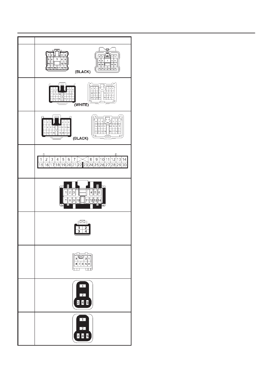
TRANSMISSION CONTROL SYSTEM (4L30–E)

7A1–89

No.

Connector face

H-17

H-18

H-19

I-1

I-9

I-18

I-46

X-3

X-10

MANUAL TRANSMISSION

7B–1

RODEO

TRANSMISSION

MANUAL TRANSMISSION MUA 5C

CONTENTS

Service Precaution

7B–1

. . . . . . . . . . . . . . . . . . . . . . 

General Description

7B–2

. . . . . . . . . . . . . . . . . . . . . 

Diagnosis

7B–4

. . . . . . . . . . . . . . . . . . . . . . . . . . . . . . 

Rear Oil Seal (4X2)

7B–5

. . . . . . . . . . . . . . . . . . . . . . 

Disassembled View

7B–5

. . . . . . . . . . . . . . . . . . . . 

Removal

7B–5

. . . . . . . . . . . . . . . . . . . . . . . . . . . . . 

Installation

7B–5

. . . . . . . . . . . . . . . . . . . . . . . . . . . . 

Transmission

7B–6

. . . . . . . . . . . . . . . . . . . . . . . . . . . 

Disassembled View

7B–6

. . . . . . . . . . . . . . . . . . . . 

Removal

7B–7

. . . . . . . . . . . . . . . . . . . . . . . . . . . . . 

Installation

7B–11

. . . . . . . . . . . . . . . . . . . . . . . . . . . . 

Transmission Case

7B–16

. . . . . . . . . . . . . . . . . . . . . . 

Major Component (4X2)

7B–16

. . . . . . . . . . . . . . . . 

Disassembly

7B–17

. . . . . . . . . . . . . . . . . . . . . . . . . . 

Reassembly

7B–18

. . . . . . . . . . . . . . . . . . . . . . . . . . 

Transmission Case and Transfer Case

7B–21

. . . . . 

Major Component (4X4)

7B–21

. . . . . . . . . . . . . . . . 

Disassembly

7B–22

. . . . . . . . . . . . . . . . . . . . . . . . . . 

Reassembly

7B–25

. . . . . . . . . . . . . . . . . . . . . . . . . . 

Intermediate Plate with Gear Assembly,
 Detent, Shift Arm, 
and Interlock Pin

7B–31

. . . . . . . . . . . . . . . . . . . . . . . . 

Disassembled View

7B–31

. . . . . . . . . . . . . . . . . . . . 

Disassembly

7B–32

. . . . . . . . . . . . . . . . . . . . . . . . . . 

Inspection and Repair

7B–33

. . . . . . . . . . . . . . . . . . 

Reassembly

7B–34

. . . . . . . . . . . . . . . . . . . . . . . . . . 

Reverse Gear and 5th Gear

7B–35

. . . . . . . . . . . . . . 

Disassembled View

7B–35

. . . . . . . . . . . . . . . . . . . . 

Disassembly

7B–36

. . . . . . . . . . . . . . . . . . . . . . . . . . 

Inspection and Repair

7B–38

. . . . . . . . . . . . . . . . . . 

Reassembly

7B–38

. . . . . . . . . . . . . . . . . . . . . . . . . . 

Top Gear Shaft, Main Gear Shaft, and
 Counter Gear Shaft

7B–44

. . . . . . . . . . . . . . . . . . . . . 

Disassmebled View

7B–44

. . . . . . . . . . . . . . . . . . . . 

Disassembly

7B–45

. . . . . . . . . . . . . . . . . . . . . . . . . . 

Inspection and Repair

7B–46

. . . . . . . . . . . . . . . . . . 

Reassembly

7B–49

. . . . . . . . . . . . . . . . . . . . . . . . . . 

Main Data and Specifications

7B–55

. . . . . . . . . . . . . 

Special Tools (MUA)

7B–59

. . . . . . . . . . . . . . . . . . . . . 

Service Precaution

WARNING: THIS VEHICLE HAS A SUPPLEMENTAL
RESTRAINT SYSTEM (SRS). REFER TO THE SRS
COMPONENT AND WIRING LOCATION VIEW IN
ORDER TO DETERMINE WHETHER YOU ARE
PERFORMING SERVICE ON OR NEAR THE SRS
COMPONENTS OR THE SRS WIRING. WHEN YOU
ARE PERFORMING SERVICE ON OR NEAR THE SRS
COMPONENTS OR THE SRS WIRING, REFER TO
THE SRS SERVICE INFORMATION. FAILURE TO
FOLLOW WARNINGS COULD RESULT IN POSSIBLE
AIR BAG DEPLOYMENT, PERSONAL INJURY, OR
OTHERWISE UNNEEDED SRS SYSTEM REPAIRS.

CAUTION: Always use the correct fastener in the
proper location. When you replace a fastener, use
ONLY the exact part number for that application.
ISUZU will call out those fasteners that require a
replacement after removal. ISUZU will also call out
the fasteners that require thread lockers or thread
sealant. UNLESS OTHERWISE SPECIFIED, do not
use supplemental coatings (Paints, greases, or other
corrosion inhibitors) on threaded fasteners or
fastener joint interfaces. Generally, such coatings
adversely affect the fastener torque and the joint
clamping force, and may damage the fastener. When
you install fasteners, use the correct tightening
sequence and specifications. Following these
instructions can help you avoid damage to parts and
systems.

SECTION

7B–2

MANUAL TRANSMISSION

General Description

A07RW039

MANUAL TRANSMISSION

7B–3

A07RW040

The MUA5C is a constant mesh transmission,
synchronized in all speeds.  The transmission is designed
for a great reduction of the shift effort and the quietest
possible operation.

Principle parts of the transmission are the integral clutch
housing, intermediate plate, the transfer case, the rear
cover, and the gears.
The transmission control box and transfer control box are
built into the transmission and transfer case.


Content   ..  1589  1590  1591  1592   ..