Isuzu Amigo / Axiom / Trooper / Rodeo / VehiCross. Manual - part 1587


  Index      Isuzu     Isuzu Amigo / Axiom / Trooper / Rodeo / VehiCross - service repair manual 1999-2002 year


Search            


Content   ..  1585  1586  1587  1588   ..


Isuzu Amigo / Axiom / Trooper / Rodeo / VehiCross. Manual - part 1587


TRANSMISSION CONTROL SYSTEM (4L30–E)

7A1–73

D

When diagnosing for a possible intermittent short or
open condition, move the wiring harness while
observing test equipment for a change.

Test Description

The numbers below refer to the step numbers on the
diagnostic chart:
5. This test measures the resistance of the component.
6. This test checks the function of the shift solenoid B

and the transmission internal wiring harness.

9.This test checks for power to the shift solenoid B

from the ignition through the PCM.

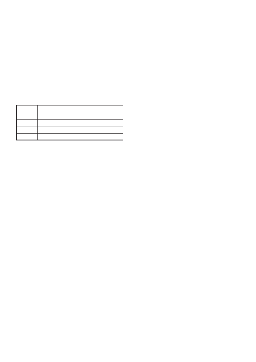
Shift Solenoid Status Chart

Gear

Shift solenoid A

Shift solenoid B

1st

OFF

ON

2nd

ON

ON

3rd

ON

OFF

4th

OFF

OFF

7A1–74 TRANSMISSION CONTROL SYSTEM (4L30–E)

DTC P0758 Shift Solenoid B Electrical 

Step

Action

Yes

No

1

Were you sent here from the “Powertrain On–Board Diagnostic
(OBD) System Check”?

Go to Step 2

Go to OBD

System Check

Refer to

Driveability and

Emission in

Engine section

2

1. Install the scan tool.
2. With the engine “on”, turn the ignition switch “on”.

NOTE: Before clearing DTC(s), use the scan tool to record “Freeze
Frame” and “Failure Records” for reference, as data will be lost
when the “Clear Info” function is used.

3. Record the DTC “Freeze Frame” and “Failure Records”.

Were DTCs P0753, P0758, P1860 set?

Go to Step 4

Go to Step 3

3

1. The engine “on”.
2. Apply brake pedal and select transmission range “D”.
3. Press and hold down the winter switch and select transmission

mode “winter”.

Does the scan tool display DTC P0758 at 3rd gear?

Go to Step 7

Go to Diagnostic

Aids

4

1. Turn the ignition “off”.
2. Disconnect the J1 (BLUE) and J2 (RED) PCM connectors.
3. Turn the ignition “on”.
4. Using the J39200 DVOM, measure the voltage between PCM

connector terminals J2–31 and J2–1.

Is the voltage within 10 – 12 volts?

Go to Step 13

Go to Step 5

5

1. Turn the ignition “off”.
2. Using the J39200 DVOM, measure the resistance between

PCM connector terminals J2–31 and J2–43.

Is the resistance within 18 – 20 ohms?

Go to Step 14

Go to Step 6

6

1. Disconnect the transmission main case connector E–54.
2. Using the J39200 DVOM, measure the resistance between

terminals E54–6(A) and E54–2(D).

Is the resistance within 18 – 20 ohms?

Go to Step 15

Go to Step 16

7

1. Turn the ignition “off”.
2. Disconnect the J1 (BLUE) and J2 (RED) PCM connectors.
3. Using the J39200 DVOM, measure the resistance between

PCM connector terminals J2–31 and J2–43.

Is the resistance within 18 – 20 ohms?

Go to Step 8

Go to Step 10

8

Using the J39200 DVOM, check a continuity between PCM
connector terminal J2–31 and ground.

Is there a continuity?

Go to Step 17

Go to Step 9

9

Using the J39200 DVOM, check a continuity between PCM
connector terminal J2–43 and ground.

Is there a continuity?

Go to Step 18

Go to Step 11

10

1. Disconnect the transmission main case connector E–54.
2. Using the J39200 DVOM, measure the resistance between

terminals E54–6(A) and E54–2(D).

Is the resistance within 18 – 20 ohms?

Go to Step 19

Go to Step 20

11

Check every connection of the PCM.

Was a problem found and corrected?

Go to Step 22

Go to Step 12

TRANSMISSION CONTROL SYSTEM (4L30–E)

7A1–75

DTC P0758 Shift Solenoid B Electrical  (Cont’d)

Step

No

Yes

Action

12

1. Connect the J1 (BLUE) and J2 (RED) PCM connectors to the

PCM.

2. Turn the ignition “on”, the engine “on”.
3. Repeat Step 3.

Does the scan tool display DTC P0758 at 3rd gear?

Go to Step 21

Go to Diagnostic

Aids

13

The wiring harness between PCM connector terminal
J2–31 and transmission main case terminal E54–6(A) is shorted
to voltage.

Was a problem found and corrected?

Go to Step 22

14

The PCM internal terminal J2–31 is shorted to voltage.
Replace the PCM. Refer to Powertrain Control Module (PCM) in
Automatic Transmission (4L30–E) section.

Is the replacement complete?

Go to Step 22

15

The wiring harness between PCM connector and transmission
main case connector is shorted.

Was a problem found and corrected?

Go to Step 22

16

The shift solenoid B is faulty, or the internal wiring harness from
the shift solenoid B is shorted.

Was a problem found and corrected?

Go to Step 22

17

The wiring harness between PCM connector terminal
J2–31 and transmission main case connector terminal E54–6(A)
is shorted to ground.

Was a problem found and corrected?

Go to Step 22

18

The wiring harness between PCM connector terminal J2–43 and
transmission main case connector terminal E54–2(D) is shorted
to ground.

Was a problem found and corrected?

Go to Step 22

19

The wiring harness between PCM connector terminal J2–31 and
transmission main case connector terminal E54–6(A), or between
PCM connector terminal J2–43 and main case connector terminal
E54–2(D) is open.

Was a problem found and corrected?

Go to Step 22

20

The internal wiring harness from the shift solenoid B is open, or
the shift solenoid B is faulty.

Was a problem found and corrected?

Go to Step 22

21

Replace the PCM.

Is the replacement complete?

Go to Step 22

22

1. After the repair is complete, use the scan tool to select “DTC”,

then “Clear Info” function and operate the vehicle under the
following conditions:

D

The shift solenoid B is commanded “on” and voltage drops to
zero.

D

The shift solenoid B is commanded “off” and voltage
increases to B+.

2. Review the scan tool “DTC Info”.

Has the last test failed or is the current DTC displayed?

Begin diagnosis

again

Go to Step 1

Repair verified
Exit DTC table

7A1–76 TRANSMISSION CONTROL SYSTEM (4L30–E)

DTC P1850 Brake Band Apply Solenoid Malfunction

D07RY00035

Circuit Description

D

The brake band apply solenoid is a normally open
solenoid which controls the flow of fluid for brake band
application.  The Powertrain Control Module (PCM)
uses Pulse Width Modulation (PWM) and changes
the duty cycle to control the solenoid.  The PCM turns
the solenoid on (energized) and off (deenergized) at a
constant frequency.  The length of time the solenoid is
energized during each on/off cycle is called the pulse
width.  By varying or “modulating” the pulse width, the
solenoid output pressure is changed.  Since the
solenoid is normally open, increasing the pulse width
increases the duty cycle and decreases the output
pressure.  PWM control provides smooth band
application without an accumulator.  The band is only
applied in first and second gears.

D

In the event of an electrical failure (open), the
solenoid regulates at the maximum oil flow (0% duty
cycle).

D

The solenoid is activated by a current.  This current is
produced by applying a voltage to one side (the High
side) and a ground to the other side (Low side).

D

The High Side Driver (HSD) is a circuit of the PCM
that acts as a switch between the solenoids and the
supply voltage.  The High side of the solenoid is
permanently supplied with voltage. When the ignition
is off, the HSD is turned off.

This DTC detects a continuous open or short to ground in
the brake band apply solenoid circuit or the brake band
apply solenoid.  This is a type “D” DTC.

Conditions For Setting The DTC

D

Battery voltage is between 10 and 16 volts.

D

Ignition is “on”, Engine “run”.

D

The PCM commands the solenoid “on” and the
voltage remains high (B+), or the PCM commands
the solenoid “off” and the voltage remains low (zero
volts).

D

All conditions met in 1.34 

 1.56 seconds.

Action Taken When The DTC Sets

D

Inhibit brake band apply solenoid.

D

The PCM will not illuminate the Malfunction Indicator
Lamp (MIL).

Conditions For Clearing The DTC

D

The DTC can be cleared from the PCM history by
using a scan tool.

D

The DTC will be cleared from history when the vehicle
has achieved 40 warmup cycles without a failure
reported.

D

The PCM will cancel the DTC default actions when
the fault no longer exists and the ignition is cycled “off”
long enough to power down the PCM.


Content   ..  1585  1586  1587  1588   ..