Isuzu Amigo / Axiom / Trooper / Rodeo / VehiCross. Manual - part 1558


  Index      Isuzu     Isuzu Amigo / Axiom / Trooper / Rodeo / VehiCross - service repair manual 1999-2002 year


Search            


Content   ..  1556  1557  1558  1559   ..


Isuzu Amigo / Axiom / Trooper / Rodeo / VehiCross. Manual - part 1558


7A–72

AUTOMATIC TRANSMISSION (4L30–E)

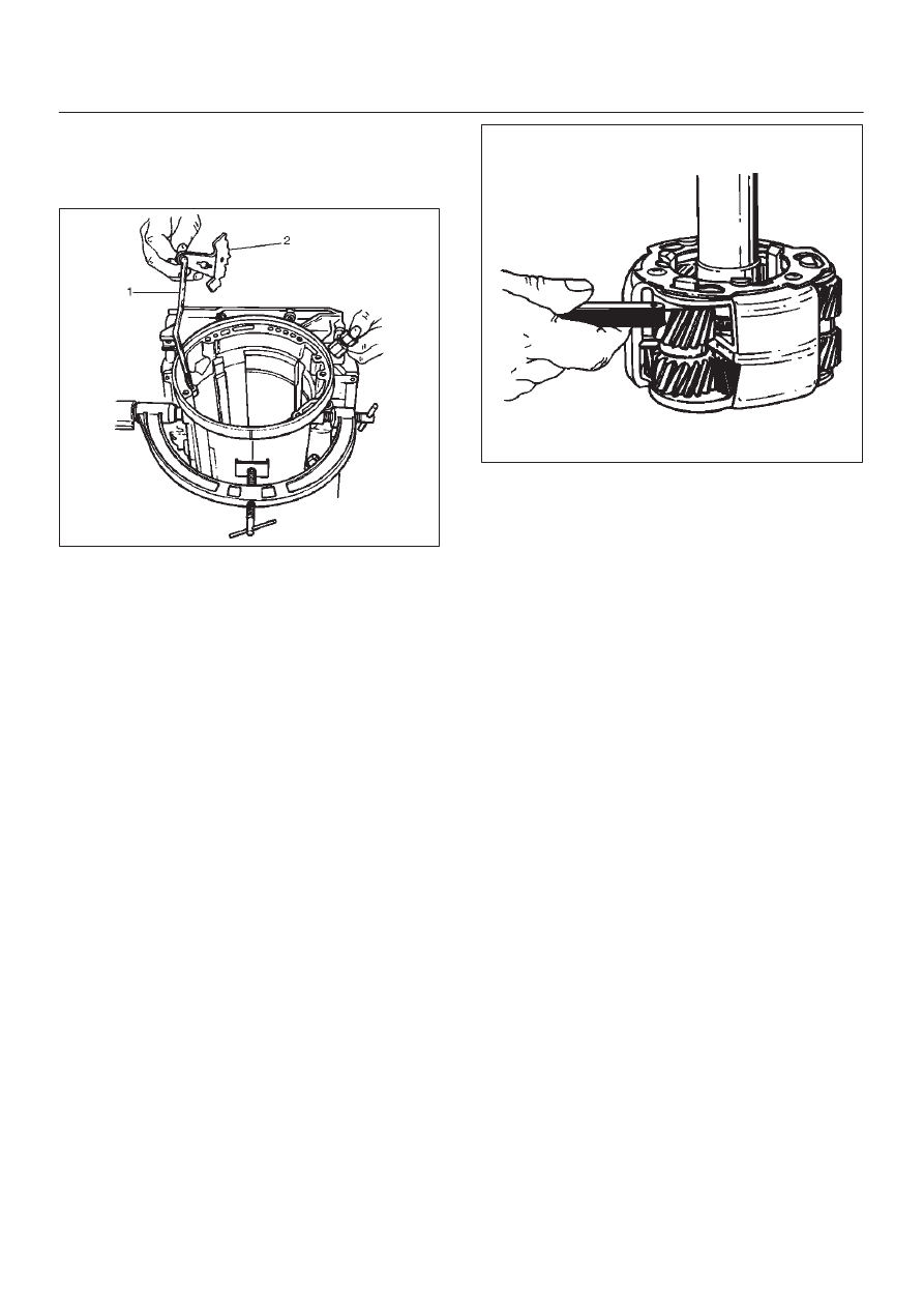
4. Install parking lock and range selector lever (2) and

new 17 mm nut. Tighten the nut to the specified
torque.

Torque: 22 N

m (16 lb ft)

249RS005

5. Rotate main case to vertical position, extension end

facing down.

D

Install brake band assembly (3).

NOTE: Be sure to align servo pin area with the servo hole.

6. Install thrust bearing (4).

NOTE: The case bushing acts as a guide for the thrust
bearing.

7. Install brake drum (5).
8. Install reaction sun gear (6).
9. Install needle bearing (7).

10. Inspect planetary carrier assembly (8) for wear and

damage. If necessary replace it.

D

Measure pinion end play clearance with a feeler
gauge.

Clearance: 0.13mm–0.89mm (0.005 in–0.035 in)

If clearance is outside specified value, replace the
planetary carrier assembly.

248RS001

11. Install the thrust bearing (9) on the output shaft.

NOTE: Use petroleum jelly to hold the thrust bearing in
place.

12. Align planetary pinions.  Each pinion is marked with

double points to indicate the master tooth space and
exactly opposite with a single point to indicate the
master tooth.  The markings on the planetary carrier
consist of double lines which are to be lined up with
the double points on two opposite pinions; the single
lines are to be lined up with the single points on the
other two pinions.

D

After all four pinions are lined up, slide on the third
clutch assembly. Rotate third clutch and check
mark alignment. Considering that the ring gear
tooth between the double points of one planetary
pinion is tooth number 1, count the teeth to check
that the single points on the two adjacent pinions
are between teeth 23 and 24 of the ring gear, and
that the ring gear tooth between the double points of
the opposite pinion is tooth number 46. If the ring
gear and pinions are not lined up, remove and
realign them.

7A–73

AUTOMATIC TRANSMISSION (4L30–E)

13. Install planetary carrier (8) with third clutch (12).

NOTE: Do not force. When properly aligned, the parts will
fit together easily.

248RS002

14. Remove the third clutch  (12).

15. Install bearing (11) and washer (10).

NOTE: Use  petroleum jelly to hold the washer and
bearing in place.

242RW002

16. Carefully align the second clutch plate inner tangs.

D

Install thrust washer, tangs pointing downward, and
locating tang positioned in slot on second clutch
hub.

NOTE: Use petroleum jelly to hold thrust washer in place.

17. Install third clutch and intermediate shaft assembly

(13) into the second clutch drum (14).

7A–74

AUTOMATIC TRANSMISSION (4L30–E)

18. Install second and third clutch assemblies into the

main case.  Twist output shaft and clutch assemblies
to ensure proper fit.

247RS001

19. Install pressure plate (15) with lip side up, tang facing

valve body face.

20. Install reverse clutch plates. Start with a steel plate

(17) and alternate with a lined plate (16).

21. Install waved clutch plate (18) with center tang facing

valve body side.

247RS002

22. Second clutch end play measurement

1. Install the J–23085–A selective washer gauging

tool (with spacer ring) on the case flange and
against the intermediate shaft.

2. Position the inner shaft of the gauging tool against

the thrust surface of the second clutch hub.

3. Tighten thumb screw.  Remove the tool.

4. Fit the spacer ring on the inner shaft of the tool.

5. Measure the gap and select appropriate washer

as shown in the chart.

Selective Thrust Washer

Gap:  mm(in)

Color

1.53 – 1.63 (0.060 – 0.064)

Yellow

1.72 – 1.82 (0.068 – 0.072)

Red

1.91 – 2.01 (0.075 – 0.079)

Black

2.10 – 2.20 (0.083 – 0.087)

Natural

2.29 – 2.39 (0.090 – 0.094)

Green

2.48 – 2.58 (0.098 – 0.102)

Blue

FOLLOWING THE PROCEDURE SHOULD
RESULT IN FINAL END–PLAY FROM 0.36 mm TO
0.79 mm (0.014 in TO 0.031 in)

247R100001

247RS004

7A–75

AUTOMATIC TRANSMISSION (4L30–E)

23. Inspect fourth clutch piston seals and replace if

necessary.

D

Lubricate J–38554 fourth clutch piston fitter and
install it on fourth clutch piston (19).

D

Install fourth clutch piston (19) in adapter case (20).

D

Remove fitter.

252RS003

24. Install retainer and spring assembly (22) into fourth

clutch piston (21).

25. Install snap ring (23) in adapter case.

D

Install J–23327 and J–23327–90 fourth clutch
spring compressor.

D

Seat snap ring in groove.

D

Remove compressor.

252RW002

252RS004

26. Install selective washer using petroleum jelly.
27. Install two O-ring seals (24) in main case and adapter

case/main case seal ring (25).

28. Install J–38588 guide pins.

D

Install adapter case and center support assembly to
main case.

242RS004


Content   ..  1556  1557  1558  1559   ..