Content .. 1555 1556 1557 1558 ..
Isuzu Amigo / Axiom / Trooper / Rodeo / VehiCross. Manual - part 1557
7A–68
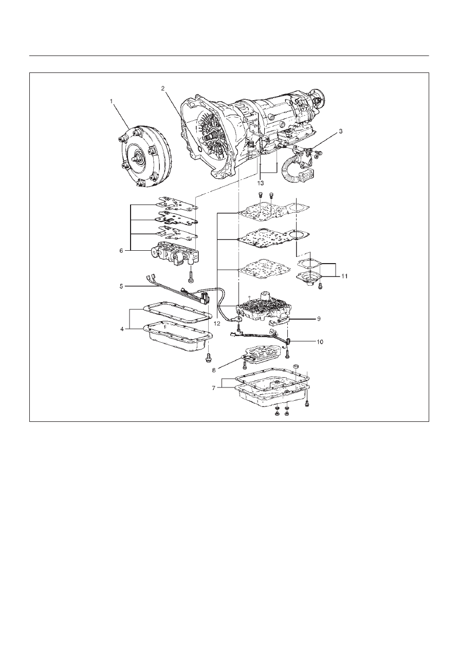
AUTOMATIC TRANSMISSION (4L30–E)
(HEC)
240R100008
14. Turn transmission to vertical position to drain fluid.
Return back to horizontal position when drained.
D
Install J–23075 servo piston spring compressor
with offset to the rear of case.
D
Compress servo piston assembly.
D
Remove servo piston retaining ring (14).
D
Slowly release servo piston assembly (15).
D
Remove tool.