Content .. 1530 1531 1532 1533 ..
Isuzu Amigo / Axiom / Trooper / Rodeo / VehiCross. Manual - part 1532
6E2–579
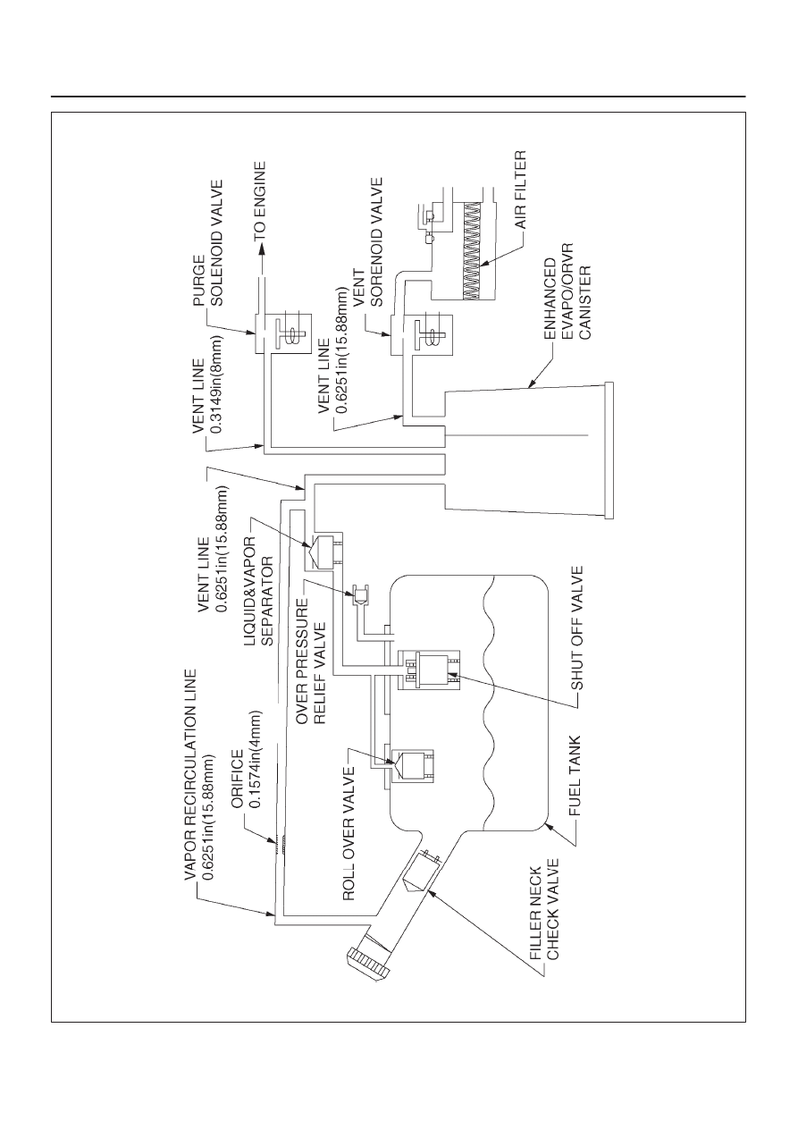
RODEO 6VD1 3.2L ENGINE DRIVEABILITY AND EMISSIONS
060R200182
Index Isuzu Isuzu Amigo / Axiom / Trooper / Rodeo / VehiCross - service repair manual 1999-2002 year
|
|
|
Content .. 1530 1531 1532 1533 ..
6E2–579 RODEO 6VD1 3.2L ENGINE DRIVEABILITY AND EMISSIONS 060R200182 |