Isuzu Amigo / Axiom / Trooper / Rodeo / VehiCross. Manual - part 1531


  Index      Isuzu     Isuzu Amigo / Axiom / Trooper / Rodeo / VehiCross - service repair manual 1999-2002 year


Search            


Content   ..  1529  1530  1531  1532   ..


Isuzu Amigo / Axiom / Trooper / Rodeo / VehiCross. Manual - part 1531


6E2–575

RODEO 6VD1 3.2L ENGINE DRIVEABILITY AND EMISSIONS

D

Vehicle speed (vehicle speed sensor).

D

PCM and ignition system supply voltage.

D

The crankshaft position (CKP) sensor sends the PCM
a 58X signal related to the exact position of the
crankshaft.

TS22909

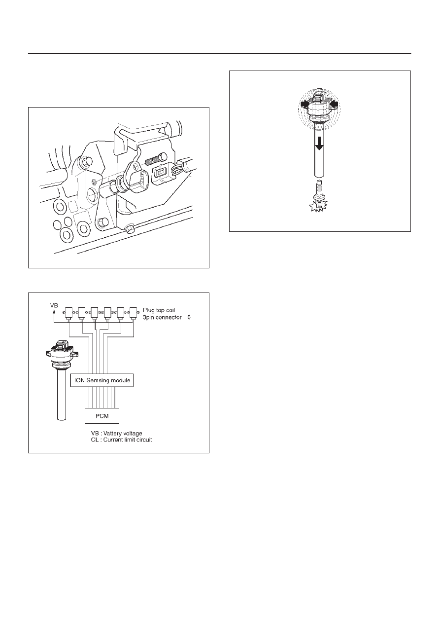
Based on these sensor signals and engine load
information,  the PCM sends 5V to each ignition coil.

060RY00116

This module has the function to energize and de-energize
the primary ignition coil in response to signals from the
PCM. The Throttle PCM controls ignition timing and dwell
time.
Continuity and out-or-range value check:
This diagnosis detects open circuit or short-circuiting in
the Electronic Spark Timing (EST) line by monitoring EST
signals. A failure determination is made when the signal
voltage remains higher or lower than the threshold for
corresponding fault code beyond a predetermined time
period.
Diagnosis enabling conditions are as follows:

D

RPM is higher than the specified threshold.

D

EST line is enabled.

060RY00029

Ignition Control PCM Output

The PCM provides a zero volt (actually about 100 mV to
200 mV) or a 5-volt output signal to the ignition control (IC)
module.  Each spark plug has its own primary and
secondary ignition coil assembly (”coil-at-plug”) located
at the spark plug itself.  When the ignition coil receives the
5-volt signal from the PCM, it provides a ground path for
the B+ supply to the primary side of the coil-at -plug
module. When the PCM shuts off the 5-volt signal to the
ION sensing module, the ground path for the primary coil
is broken.  The magnetic field collapses and induces a
high voltage secondary impulse which fires the spark plug
and ignites the air/fuel mixture.
The circuit between the PCM and the ignition coil is
monitored for open circuits, shorts to voltage, and shorts
to ground.  If the PCM detects one of these events, it will
set one of the following DTCs:

D

P0351:  Ignition coil Fault on Cylinder #1

D

P0352:  Ignition coil Fault on Cylinder #2

D

P0353:  Ignition coil Fault on Cylinder #3

D

P0354:  Ignition coil Fault on Cylinder #4

D

P0355:  Ignition coil Fault on Cylinder #5

D

P0356:  Ignition coil Fault on Cylinder #6

Powertrain Control Module (PCM)

The PCM is responsible for maintaining proper spark and
fuel injection timing for all driving conditions.  To provide
optimum driveability and emissions, the PCM monitors
the input signals from the following components in order
to calculate spark timing:

D

Engine coolant temperature (ECT) sensor.

D

Intake air temperature (IAT) sensor.

D

Mass air flow (MAF) sensor.

D

PRNDL input from transmission range switch.

D

Throttle position (TP) sensor.

D

Vehicle speed sensor (VSS) .

6E2–576

RODEO 6VD1 3.2L ENGINE DRIVEABILITY AND EMISSIONS

D

Crankshaft position (CKP) sensor.

Spark Plug

Although worn or dirty spark plugs may give satisfactory
operation at idling speed, they frequency fail at higher
engine speeds.  Faulty spark plugs may cause poor fuel
economy, power loss, loss of speed, hard starting and
generally poor engine performance.  Follow the
scheduled maintenance service recommendations to
ensure satisfactory spark plug performance.  Refer to
Maintenance and Lubrication section.
Normal spark plug operation will result in brown to
grayish-tan deposits appearing on the insulator portion of
the spark plug.  A small amount of red-brown, yellow, and
white powdery material may also be present on the
insulator tip around the center electrode.  These deposits
are normal combustion by-products of fuels and
lubricating oils with additives.  Some electrode wear will
also occur.  Engines which are not running properly are
often referred to as “misfiring.”  This means the ignition
spark is not igniting the air/fuel mixture at the proper time.
While other ignition and fuel system causes must also be
considered, possible causes include ignition system
conditions which allow the spark voltage to reach ground
in some other manner than by jumping across the air gap
at the tip of the spark plug, leaving the air/fuel mixture
unburned.  Refer to 

DTC P0300.  Misfiring may also occur

when the tip of the spark plug becomes overheated and
ignites the mixture before the spark jumps. This is
referred to as “pre-ignition.”
Spark plugs may also misfire due to fouling, excessive
gap, or a cracked or broken insulator.  If misfiring occurs
before the recommended replacement interval, locate
and correct the cause.
Carbon fouling of the spark plug is indicated by dry, black
carbon (soot) deposits on the portion of the spark plug in
the cylinder.   Excessive idling and slow speeds under
light engine loads can keep the spark plug temperatures
so low that these deposits are not burned off. Very rich
fuel mixtures or poor ignition system output may also be
the cause.  Refer to DTC P0172.
Oil fouling of the spark plug is indicated by wet oily
deposits on the portion of the spark plug in the cylinder,
usually with little electrode wear.  This may be caused by
oil during break-in of new or newly overhauled engines.
Deposit fouling of the spark plug occurs when the normal
red-brown, yellow or white deposits of combustion by
products become sufficient to cause misfiring.  In some
cases, these deposits may melt and form a shiny glaze on
the insulator around the center electrode.  If the fouling is
found in only one or two cylinders, valve stem clearances
or intake valve seals may be allowing excess lubricating
oil to enter the cylinder, particularly if the deposits are
heavier on the side of the spark plug facing the intake
valve.

TS23995

Excessive gap means that the air space between the
center and the side electrodes at the bottom of the spark
plug is too wide for consistent firing.  This may be due to
improper gap adjustment or to excessive wear of the
electrode during use.  A spark plug gap that is too small
may cause an unstable idle condition.  Excessive gap
wear  can be an indication of continuous operation at high
speeds or with engine loads, causing the spark to run too
hot.  Another possible cause is an excessively lean fuel
mixture.

TS23992

Low or high spark plug installation torque or improper
seating can result in the spark plug running too hot and
can cause excessive center electrode wear.  The plug
and the cylinder head seats must be in good contact for
proper heat transfer and spark plug cooling.  Dirty or
damaged threads in the head or on the spark plug can
keep it from seating even though the proper torque is
applied.  Once spark plugs are properly seated, tighten
them to the torque shown in the Specifications Table.  Low
torque may result in poor contact of the seats due to a
loose spark plug.  Overtightening may cause the spark
plug shell to be stretched and will result in poor contact

6E2–577

RODEO 6VD1 3.2L ENGINE DRIVEABILITY AND EMISSIONS

between the seats.  In extreme cases,  exhaust blow-by
and damage beyond simple gap wear may occur.
Cracked or broken insulators may be the result of
improper installation, damage during spark plug
re-gapping, or heat shock to the insulator material.  Upper
insulators can be broken when a poorly fitting tool is used
during installation or removal, when the spark plug is hit
from the outside, or is dropped on a hard surface. Cracks
in the upper insulator may be inside the shell and not
visible. Also, the breakage may not cause problems until
oil or moisture penetrates the crack later.

TS23994

A/C Clutch Diagnosis

A/C Clutch Circuit Operation

A 12-volt signal is supplied to the A/C request input of the
PCM when the A/C is selected through the A/C control
switch.
The A/C compressor clutch relay is controlled through the
PCM.  This allows the PCM to modify the idle air control
position prior to the A/C clutch engagement for better idle
quality.  If the engine operating conditions are within their
specified calibrated acceptable ranges, the PCM will
enable the A/C compressor relay.  This is done by
providing a ground path for the A/C relay coil within the
PCM.  When the A/C compressor relay is enabled,
battery voltage is supplied to the compressor clutch coil.
The PCM will enable the A/C compressor clutch
whenever the engine is running and the A/C has been
requested.  The PCM will not enable the A/C compressor
clutch if any of the following conditions are met:

D

The throttle is greater than  90%.

D

The engine speed is greater than 6315 RPM.

D

The ECT is greater than 119

°

C (246

°

F).

D

The IAT is less than 5

°

C (41

°

F).

D

The throttle is more than 80% open.

A/C Clutch Circuit Purpose

The A/C compressor operation is controlled by the
powertrain control module (PCM) for the following
reasons:

D

It improvises idle quality during compressor clutch
engagement.

D

It improvises wide open throttle (WOT) performance.

D

It provides A/C compressor protection from operation
with incorrect refrigerant pressures.

The A/C electrical system consists of the following
components:

D

The A/C control head.

D

The A/C refrigerant pressure switches.

D

The A/C compressor clutch.

D

The A/C compressor clutch relay.

D

The PCM.

A/C Request Signal

This signal tells the PCM when the A/C mode is selected
at the A/C control head.  The PCM uses this to adjust the
idle speed before turning on the A/C clutch.  The A/C
compressor will be inoperative if this signal is not
available to the PCM.
Refer to 

A/C Clutch Circuit Diagnosis section for A/C

wiring diagrams and diagnosis for A/C electrical system.

General Description (Evaporative
(EVAP) Emission System)

EVAP Emission Control System Purpose

The basic evaporative emission (EVAP) control system
used on all vehicles is the charcoal canister storage
method.  Gasoline vapors from the fuel tank flow into the
canister through the inlet labeled “TANK.” These vapors
are absorbed into the activated carbon (charcoal) storage
device (canister) in order to hold the vapors when the
vehicle is not operating.  The canister is purged by PCM
control when the engine coolant temperature is over 60

°

C

(140

°

F), the IAT reading is over 10

°

C (50

°

F),  and the

engine has been running.  Air is drawn into the canister
through the air inlet grid.  The air mixes with the vapor and
the mixture is drawn into the intake manifold.

EVAP Emission Control System Operation

The EVAP canister purge is controlled by a solenoid valve
that allows the manifold vacuum to purge the canister.
The powertrain control module (PCM) supplies a ground
to energize the solenoid valve (purge on).  The EVAP
purge solenoid control is pulse-width modulated (PWM)
(turned on and off several times a second).  The duty
cycle (pulse width) is determined by engine operating
conditions including load, throttle positron, coolant
temperature and ambient temperature.  The duty cycle is
calculated by the PCM.  The output is commanded when
the appropriate conditions have been met.  These
conditions are:

D

The engine is fully warmed up.

D

The engine has been running for a specified time.

D

The IAT reading is above 10

°

C (50

°

F).

6E2–578

RODEO 6VD1 3.2L ENGINE DRIVEABILITY AND EMISSIONS

 A continuous purge condition with no purge commanded
by the PCM will set a DTC P1441.
Poor idle, stalling and poor driveability can be caused by:

D

A malfunctioning purge solenoid.

D

A damaged canister.

D

Hoses that are split, cracked, or not connected
properly.

Enhanced Evaporative Emission Control
System

The basic purpose of the Enhanced Evaporative
Emissions control system is the same as other EVAP
systems.  A charcoal-filled canister captures and stores
gasoline fumes.  When the PCM determines that the time
is right, it opens a purge valve which allows engine
vacuum to draw the fumes into the intake manifold.
The difference between this and other systems is that the
PCM monitors the vacuum and/or pressure in the system
to determine if there is any leakage. If the PCM
determines that the EVAP system is leaking or not
functioning properly, it sets a Diagnostic Trouble Code
(DTC) in the PCM memory.
The enhanced EVAP system is required to detect
evaporative fuel system leaks as small as 0.020 in. (1.0
mm) between the fuel filler cap and purge solenoid.  The
system can test the evaporative system integrity by
applying a vacuum signal (ported or manifold) to the fuel
tank to create a small vacuum.  The PCM then monitors
the ability of the system to maintain the vacuum.  If the
vacuum remains for a specified period of time, there are
no evaporative leaks and a PASS report is sent to the
diagnostic executive.  If there is a leak, the system either
will not achieve a vacuum, or a vacuum cannot be
maintained.  Usually, a failure can only be detected after a
cold start with a trip of sufficient length and driving
conditions to run the needed tests.  The enhanced EVAP
system diagnostic will conduct up to eight specific
sub-tests to detect fault conditions.  If the diagnostic fails
a sub-test, the PCM will store a Diagnostic Trouble Code
(DTC) to indicate the type of detected.


Content   ..  1529  1530  1531  1532   ..