Isuzu Amigo / Axiom / Trooper / Rodeo / VehiCross. Manual - part 1494


  Index      Isuzu     Isuzu Amigo / Axiom / Trooper / Rodeo / VehiCross - service repair manual 1999-2002 year


Search            


Content   ..  1492  1493  1494  1495   ..


Isuzu Amigo / Axiom / Trooper / Rodeo / VehiCross. Manual - part 1494


6E2–427

RODEO 6VD1 3.2L ENGINE DRIVEABILITY AND EMISSIONS

Diagnostic Trouble Code (DTC) 

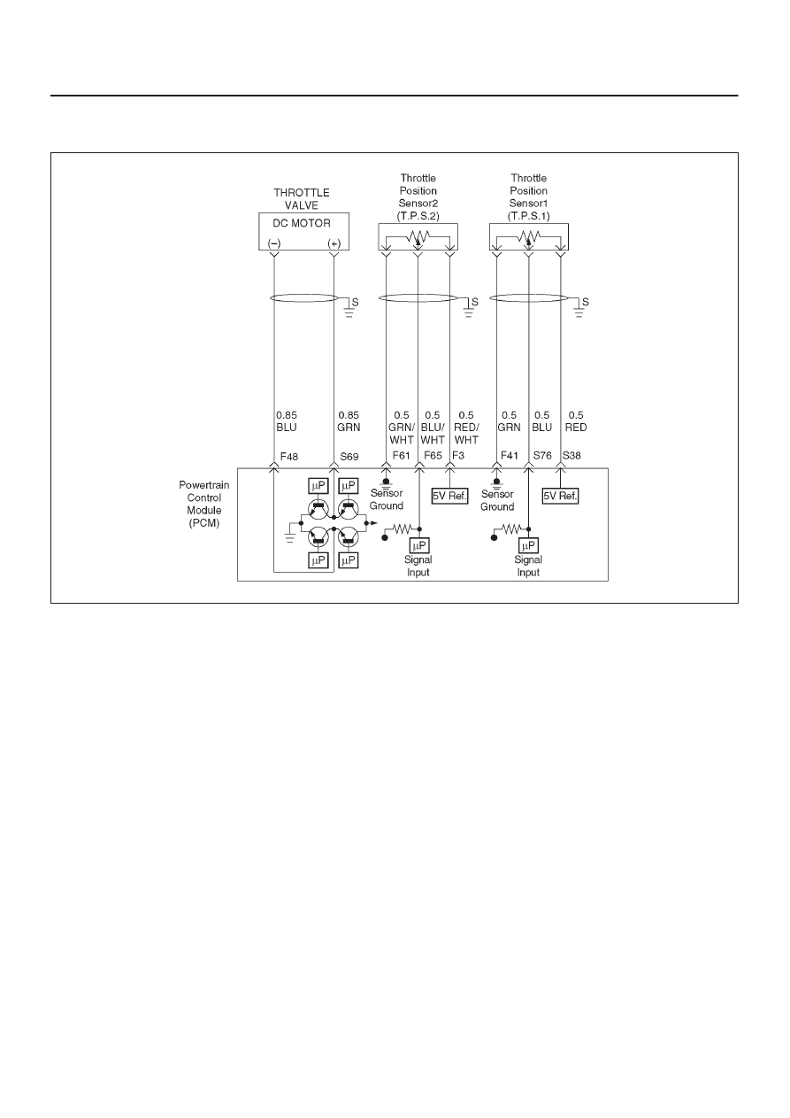
P1220 Throttle Position Senser2 (TPS2) Circuit Fault

D06RY00111

Circuit Description

D

The throttle position (TP2) sensor circuit provides a
voltage signal relative to throttle blade angle.
The throttle blade angle will vary about 8 % at closed
throttle to about 92 % at wide open throttle (WOT).

This code detects a continuous short to ground or
high in either the cicuit or the sensor.

Conditions for setting the DTC

D

The Ignition is “ON”.

D

The throttle blade angle is less than 2.5 % or more tnan
97.5 % for 18 failres within 500 test samples (15.6m
sec).

Action Taken When the DTC Sets

D

The PCM will store condition which were present when
the DTC was set as Freeze Frame and in the Failure
Records data.

Conditions for Clearing the MIL/DTC

D

The PCM will turn the MIL “OFF” on the third
consecutive trip cycle during which the diagnostic has
been run and the fault condtion is no longer present.

D

A history DTC P1120 will clear after 40 consecutive trip
cycle during which the warm up cycles have occurred
without a fault.

D

DTC P1120 can be cleared using the Tech2 “Clear Info”
function or by disconnecting the PCM battery feed.

Diagnostic Aids

An intermittent may be caused by the following:

D

Poor connectons.

D

Mis routed harness.

D

Rubbed through wire insulation.

D

Broken wire inside the insulation.

Check for the following conditions:

D

The CKP sensor shares 5 Volt reference with the TP
sensor 2. If these codes are also set, it could indicate
a problem with the 5 Volt reference curcuit.

D

Poor connection at PCM-Inspect harness connectors
for backed out terminals,improper mating,broken
locks, improperly formed or damaged terminals,and
poor terminal to wire connection.

D

Damaged harness–Inspect the wiring harness for
damage. If the harness appears to be OK,observe the
TP sensor display on the Tech 2 while moving
connectors and wiring harnesses related to the sensor.
A change in the display will indicate the location of
the fault. If DTC P1120 cannot be duplicated,the
information included in the Faillure Records data can
be useful in determined vehicle mileage since the
DTC was last set.

If it is determined that the DTC occurs
intermittently,performing the DTC

P1120 Diagnostic Chart may isolate the cause of the fault.

6E2–428

RODEO 6VD1 3.2L ENGINE DRIVEABILITY AND EMISSIONS

DTC P1220-TPS 2 Circuit Fault


Step

Action

Value(s)

Yes

No

1

Was the “On-Board (OBD) System Check” performed?

Go to

 Step 2

Go to

 OBD

System

Check

2

Was the “Electric Throttle Control (ETC) System
Check” performed?

Go to

 Step 3

Go to

 ETC

System

Check

3

1. Disconnect the CKP sensor.
2. Connect a test 5 volt reference circuit and the CKP

signal at the CKP sensor harness connector.

3. Observe the CKP reading on the DVM.

Is the CKP reading less than the specified value? (If no,
start with diagnosis chart for other sensors in the circuit
and see if 5V returns.)

5V

Go to

 Step 5

Go to

 Step 4

4

1. Check the CKP signal circuit between the PCM and

CKP ground circuit.

2. If the CKP signal circuit is open or shorted, repair as

necessary.

Was the CKP signal circuit open or shorted?

Verify repair

Go to

 Step 6

5

Replace the CKP sensor.

Is the action complete?

Verify repair

6

1. Ignition “ON”, engine not running.
2. Observe the AP2 reading on the Tech2.

Is the AP2 reading less than the specified value?

Idle position =

85

89%

Open throttle

= 11

15%

Go to

 Step 7

Go to

 Step 10

7

1. Disconnect the AP sensor 2.
2. Connect the Tech2  5 Volt reference circuit and the

AP2 signal at the Ap2 sensor harness connector.

3. Observe the AP2 reading on the Tech 2.

Is the AP2 reading less than the specified value? (If no,
start with diagnosis chart forother sensors in the circuit
and see if 5V returns.)

Go to

 Step 9

Go to

 Step 8

8

1. Check the Ap2 sensor signal circuit between the

PCM and AP2 sensor grund circuit.

2. If the AP2 sensor signal circuit open or shoted,

repair it as necessary.

Was the AP2 sensor signal circuit open or shorted?

Verify repair

Go to

 Step 16

9

Replace the AP sensor 2.

Is the action complete?

Verify repair

10

Observe the TP angle reading on the Tech-2 while
slowly opening the throttle.

Does the TP angle increase steadily and evenly from
the closed throttle value to the wide open throttle
value?

Closed TP
sensor 1 =
8

13% TP

sensor 2 =

8

13% Wide

open TP

sensor 1 =

87

97% TP

sensor 2 =

87

97%

Go to

 Step 11

Go to

 Step 12

6E2–429

RODEO 6VD1 3.2L ENGINE DRIVEABILITY AND EMISSIONS

DTC P1220-TPS 2 Circuit Fault

  (Cont'd)

Step

No

Yes

Value(s)

Action

11

Was the DTC P1220 stored?

Go to

 Step 16

Refer to

Diagnostic

Aids

12

1. Connect a DVM between the 5Volt reference circuit

and the TP2 sensor ground circuit at the TPsensor
harness connector.

2. Observe the voltage using a DVM.

Is the voltage near the specified value?

5V

Go to

 Step 13

Go to

 Step 16

13

Check the following items;

1. TP2 signal circuit for a short to voltage.
2. TP2 sensor ground circuit for high resistance

between the PCM and the TP2 sensor.

3. TP2 sensor ground circuit for a poor connection.
4. If a problem is found,repair wiring harness as

necessary.

Was a problem found?

Verify repair

Go to

 Step 14

14

Check the following items;

1. TP2 signal circuit or 5 volt reference circuit for a

poor connection.

2. TP2 signal circuit or 5 volt reference circuit for high

resistance between the PCM and the TP sensor.

3. If a problem is found, repair wiring harness as

necessary.

Was a problem found?

Verify repair

Go to

 Step 15

15

Replace the TP sensor.

Was a problem corrected?

Verify repair

Go to

 Step 16

16

Replace the PCM.

IMPORTANT: The replacement PCM must be
programmed. Refer to

 ON-Vehicle Service in Power

Control Module and Sensors for procedures.

And also refer to latest Service Bulletin. Check to see
if the latest software is released or not.

And then Down Load the LATEST PROGRAMMED
SOFTWARE to the replasement PCM.

Is the action complete?

Verify repair

6E2–430

RODEO 6VD1 3.2L ENGINE DRIVEABILITY AND EMISSIONS

Diagnosis Truble Code(DTC) 

P1221 TPS1 – TPS2 correlation(Circuit Performance)

060R200069

Circuit Description

D

The powertrain control module (PCM) controls engine
speed by adjusting the position of the throttle control
valve (DC motor). The throttle motor is a DC motor
driven by one coil. The PCM applies current to DC
motor coil in steps (%) to adjustment the valve into a
passage in the throttle body to air flow.
This method allows highly accurate control of engine
speed and quick response to changes in engine
load.

D

The acceleration position (AP) sensor circuit provides
a voltage signal relative to acceleration pedal angle.
The acceleration pedal angle (AP1) will vary about
13% at idle position to about 87% at open
throttle(WOT).

APS signal is used to determine which DC will
adjusting throttle position.

After the APS signal has been processed by the
PCM, it will command DC motor to allow a move of
throttle position.

D

Acceleration pedal – Check for objects blocking the AP
sensor or pedal arm with spring, and excessive
deposits in the acceleration pedal arm and on the
acceleration pedal.

Diagnostic Aids

D

An intermittent may be caused by a poor connection,
rubbed–through wire insulation or a wire broken inside
the insulation. Check for poor connections or a
damaged harness. Inspect the PCM harness and
connector for improper mating, broken locks,
improperly formed or damaged terminals, poor
terminal-to-wire connection, and damaged harness.

D

Throttle body – Check for objects blocking the DC
motor or throttle bore, excessive deposits in the ETC
passage and on the valve spring, and excessive
deposits in the throttle bore and on the throttle valve
plate.


Content   ..  1492  1493  1494  1495   ..