Isuzu Amigo / Axiom / Trooper / Rodeo / VehiCross. Manual - part 144


  Index      Isuzu     Isuzu Amigo / Axiom / Trooper / Rodeo / VehiCross - service repair manual 1999-2002 year


Search            


Content   ..  142  143  144  145   ..


Isuzu Amigo / Axiom / Trooper / Rodeo / VehiCross. Manual - part 144


4C–76

DRIVE SHAFT SYSTEM

Spline

The nylon-coated spline should be free from nicks and
dings and the underlying steel spline should not be visible.
After cleaning the nylon coating spline, the coating should
exhibit only slight indicator of wear.
Grease volume is approximately 10 grams of grease in
total.  Grease should be evenly applied to both the female
and  the male slip splines using a small brush.  After
assembly of the slip joint, the sliding joint should be fully
worked from the full collapsed to the full extended
position.

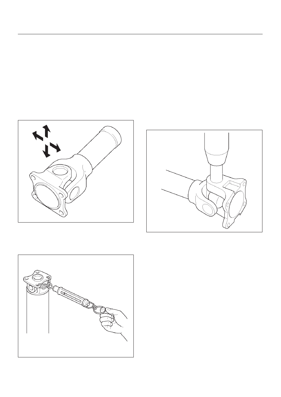
Play in the universal joint

Limit: Less  than 0.15 mm (0.006 in)

401RW023

Preload of the universal joint

Preload should be 0 to 49 N(0 to11.0 lb).  Joints should
rotate smoothly and freely and should exhibit no rough or
ratchety movement.

401RW019

Universal Joint Reassembly

1. Install spider to flange yoke. Be sure to install the

spider by aligning the setting marks made during
disassembly.

2. Pack the four grease cavities of the spider with a high

quality, extreme pressure N.L.G.I. Grade 2 grease.
Do not add additional grease to the bearing cup
assembly.

3. Move one end of the spider to cause a trunnion to

project through the spider hole beyond the outer
machined face of the yoke lug.  Place a bearing over
the trunnion diameter and align it to the spider hole.
Using an arbor press, hold the trunnion in alignment
with the spider hole and place a solid plug on the
upper bearing.  Press the bearing into the spider hole
enough to install a snap ring.

401RW020

4. Install a snap ring.

Be sure the snap rings are properly seated in the
grooves.

5. Repeat steps 3 and 4 to install the opposite bearing.  If

the joint is stiff, strike the yoke ears with a soft
hammer to seat needle bearings.

4C–77

DRIVE SHAFT SYSTEM

6. Align setting marks (1) and join the yokes.

401RW018

7. Install snap ring.

Reassembly

401RW032

Legend

(1) Sleeve Yoke
(2) Clamp

(3) Boot
(4) Clamp
(5) Tube Assembly

4C–78

DRIVE SHAFT SYSTEM

1. Apply grease evenly to both the female and male

splines.

2. Apply a small amount of grease by finger to the outer

lips of the boot.

3. Slide the boot onto the yoke shaft being careful not to

damage the spline coating or boot.

4. Insert the yoke shaft spline into the sleeve being

careful to maintain proper phasing.  The spider holes
should be in line and as per originally marked prior to
disassembly.

5. Position boot onto sleeve and yoke shaft in final

position over boot grooves.

6. Attach boot clamps and secure using pliers.
7. Be sure clamp is properly seated and secure.

Main Data and Specifications

General Specifications

Transmission

M/T

A/T

Length (between two spiders
center)

367.2 mm (14.81 in)

542.2 mm (21.35 in)

Torque Specifications

401RX001

4C–79

DRIVE SHAFT SYSTEM

Rear Propeller Shaft

Rear Propeller Shaft and Associated Parts

401RX003

Legend

(1) Bolt, Nut and Washer (Transfer Side)

(2) Rear Propeller Shaft
(3) Bolt, Nut and Washer (Rear Axle Side)

Removal

1. Raise the vehicle on a hoist.

NOTE: Apply alignment marks on the flange at the rear
propeller shaft both front and rear side.

2. Remove transfer side bolt, nut and washer (except

spline yoke type).

3. Remove rear axle side bolt, nut and washer.
4. Remove rear propeller shaft.

NOTE: Plug the hole of the transmission rear end to
prevent oil leakage (spline yoke type only).

Installation

NOTE: Never install the shaft assembly backwards.
Never insert bar between yoke lugs when tightening or re-
moving bolts.
Completely remove the dust or foreign matter from the
connecting surface of flange coupling on each end of the
propeller shaft.

1. Align the mark which is applied at removal.
2. Install rear propeller shaft and tighten the bolts to the

specified torque.

Torque: 63 N·m(46 lb ft)


Content   ..  142  143  144  145   ..