Isuzu Amigo / Axiom / Trooper / Rodeo / VehiCross. Manual - part 139


  Index      Isuzu     Isuzu Amigo / Axiom / Trooper / Rodeo / VehiCross - service repair manual 1999-2002 year


Search            


Content   ..  137  138  139  140   ..


Isuzu Amigo / Axiom / Trooper / Rodeo / VehiCross. Manual - part 139


4C–56

DRIVE SHAFT SYSTEM

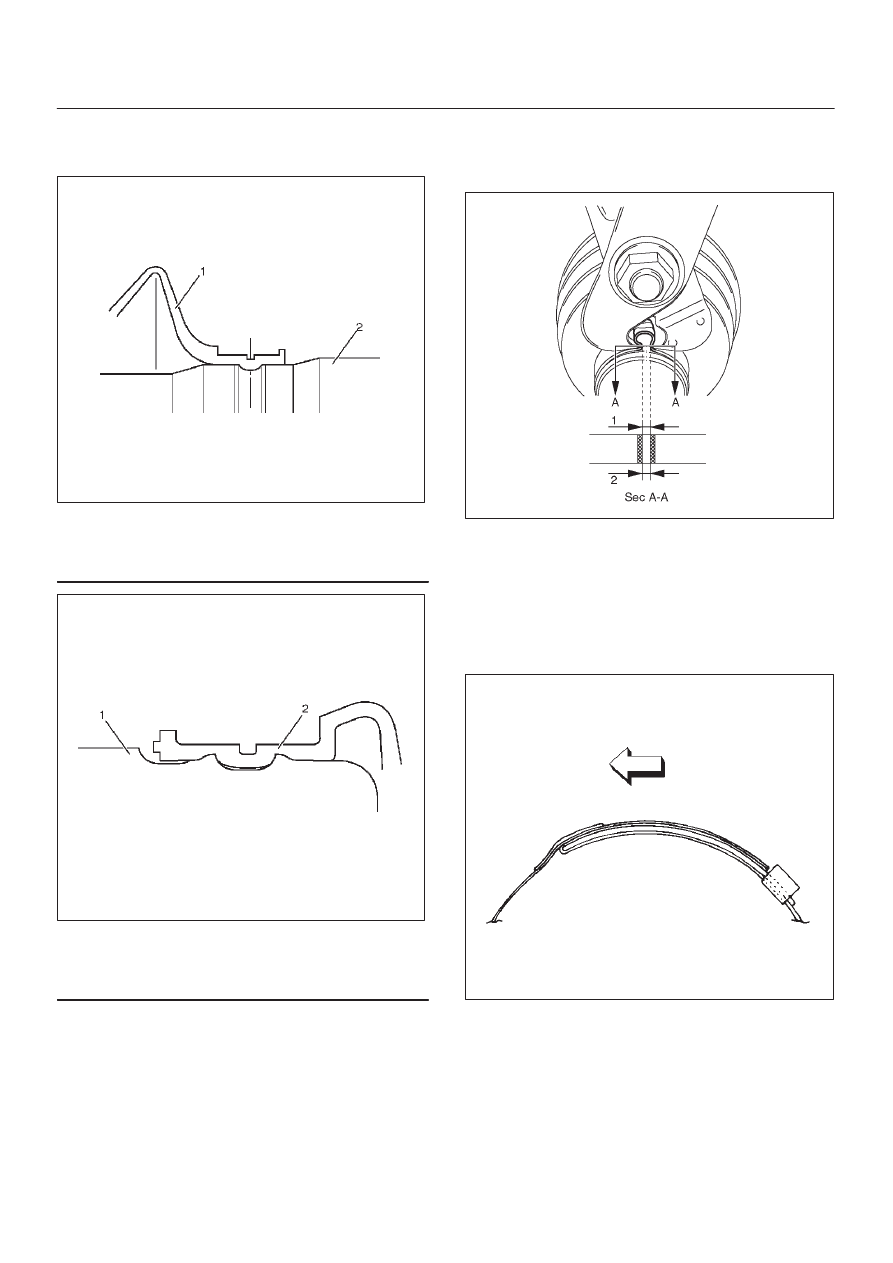
CAUTION: During bellows assembly, be sure to
insert both ends of the bellows into the BJ ASM and
shaft grooves.

412R100007

Legend

(1) Bellows
(2) Shaft

412R100013

Legend

(1) BJ ASM
(2) Bellows

8. Install band. Note the setting direction.  After

installation, check Standard Caulk Measure.Use the
special tool pliers J–35910 to caulk the bands to the
specified value.

412R100012

Standard Caulk Measure

D

1.2mm (0.05in) <= (1) and (2) <= 4.0mm (0.16in)

D

(1) – (2) or (2) – (1) <= 0.4mm (0.016in)

9. Install another bellows and fix band.

10. Install band. Note the setting direction.  After

installation, check that the bellows is free from
distortion. (DOJ SIDE ONLY)

412RS017

11. Install another bellows and fix band.

12. Install the ball guide with the smaller diameter side

ahead onto the shaft.

4C–57

DRIVE SHAFT SYSTEM

13. Install ball retainer.
14. Using snap ring pliers, install the snap ring (1)

securing the ball retainer to the shaft.

412RS013

15. Align the track on the ball (1) retainer with the window

in the cage, and install the six balls into position.

412RS018

16. Pack 150g of the specified grease in DOJ case, then

install drive shaft joint assembly. After reassembly,
move the DOJ longitudinally several times to get to fit.

17. Install the circlip (1) so that open ends are positioned

away from the ball groove.

412RS019

412RS020

Legend

(1) Outer Case
(2) Circlip
(3) Open Ends

4C–58

DRIVE SHAFT SYSTEM

18. Install bellows. Adjust the air pressure within the

bellows by inserting a screwdriver or equivalent, so
that it equals atmospheric pressure.

412RS021

19. Install band. After installation, check that the bellows

is free from distortion.

4C–59

DRIVE SHAFT SYSTEM

Shift On The Fly System

Shift On The Fly System and Associated Parts

412RY00007

Legend

(1) Filler Plug
(2) Bolt
(3) Oil Seal
(4) Snap Ring(External)
(5) Inner Shaft Bearing
(6) Snap Ring(Internal)
(7) Inner Shaft

(8) Needle Bearing
(9) Clutch Gear

(10) Sleeve

(11) Housing

(12) Front Axle Drive Shaft(LH side) with Bracket
(13) Bolt
(14) Actuator Assembly
(15) Bolt

Disassembly

1. Remove filler plug and gasket, drain oil.
2. Loosen mounting bracket fitting bolts and remove

front axle drive shaft from front axle case.

3. Remove actuator assembly and draw out actuator

ASM.

4. Remove housing.
5. Remove sleeve.
6. Remove clutch gear.


Content   ..  137  138  139  140   ..