Content .. 1383 1384 1385 1386 ..
Isuzu Amigo / Axiom / Trooper / Rodeo / VehiCross. Manual - part 1385
6D3–16
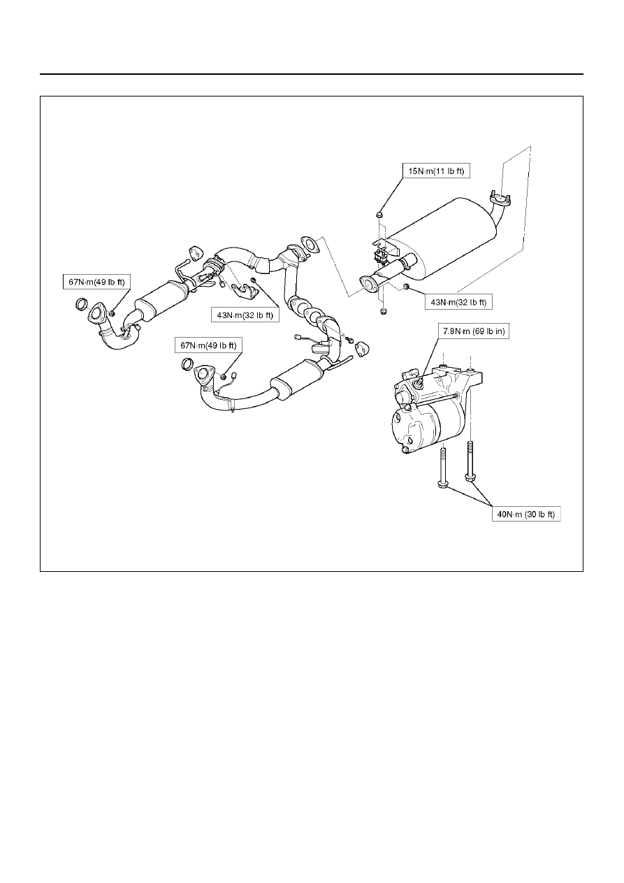
STARTING AND CHARGING SYSTEM (6VD1 3.2L)
150R100012
Index Isuzu Isuzu Amigo / Axiom / Trooper / Rodeo / VehiCross - service repair manual 1999-2002 year
|
|
|
Content .. 1383 1384 1385 1386 ..
6D3–16 STARTING AND CHARGING SYSTEM (6VD1 3.2L) 150R100012 |