Isuzu Amigo / Axiom / Trooper / Rodeo / VehiCross. Manual - part 1358


  Index      Isuzu     Isuzu Amigo / Axiom / Trooper / Rodeo / VehiCross - service repair manual 1999-2002 year


Search            


Content   ..  1356  1357  1358  1359   ..


Isuzu Amigo / Axiom / Trooper / Rodeo / VehiCross. Manual - part 1358


6A–36

ENGINE MECHANICAL (6VD1 3.2L)

Valve Stem Oil Controller , Valve Spring and Valve Guide

Removal

1. Disconnect battery ground cable.
2. Drain engine oil.

D

Drain engine coolant.

3. Remove cylinder head assembly.

D

Refer to removal procedure for Cylinder Head in
this manual.

4. Remove camshaft.

D

Refer to removal procedure for Camshaft in this
manual.

5. Remove tappets with shim.

NOTE: Do not damage shim surface.

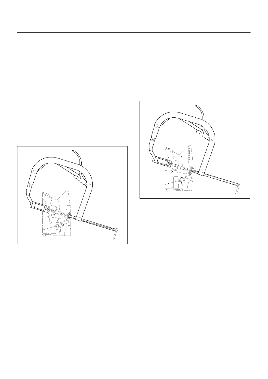
6. Remove valve springs using J-8062 valve spring

compressor and J-42898 valve spring compressor
adapter then remove upper valve spring seat and
lower seat.

014RW042

7. Remove oil controller using J-37281 oil controller

remover, remove each valve stem oil controller.

8. Remove valve guide using J-37985 valve guide

replacer.

Installation

1. Install valve guide using J-42899 valve guide installer.
2. Install oil controller using J-38537 oil controller

installer.

3. Install lower valve spring seat, valve spring and upper

valve spring seat then put split collars on the upper
spring seat, using J-8062 valve spring compressor
and J-42898 valve spring compressor adapter to
install the split collars.

014RW042

4. Install tappet with shim.
5.  Install camshaft assembly.

D

Refer to installation procedure for Camshaft in this
manual.

6. Install cylinder head assembly.

D

Refer to installation procedure for Cylinder Head in
this manual.

7. Fill engine oil until full level.
8. Fill engine coolant.

6A–37

ENGINE MECHANICAL (6VD1 3.2L)

Piston, Piston Ring and Connecting Rod

Removal

F06RW011

Legend

(1) Cylinder Head
(2) Crankcase with Oil Pan
(3) Oil Pipe

(4) Oil Strainer
(5) Oil Gallery
(6) Piston with Connecting Rod Assembly

1. Remove cylinder head assembly.

D

Refer to removal procedure for Cylinder Head in
this manual.

2. Remove crankcase with oil pan.

D

Refer to removal procedure for Oil Pan and
Crankcase in this manual.

6A–38

ENGINE MECHANICAL (6VD1 3.2L)

3. Remove oil strainer fixing bolts, remove oil strainer

assembly with O-ring.

050RW002

Legend

(1) Oil Pump
(2) Oil Strainer
(3) Oil Gallery
(4) From Oil Filter
(5) To Oil Filter

4. Remove three fixing bolts, oil pipe with O-ring.
5. Remove eight fixing bolts, oil gallery.
6. Remove piston with connecting rod assembly.

(before removing the bearing cap, remove carbon on
the top of cylinder bore and push piston with
connecting rod out from the top of cylinder bore.)

Installation

1. Install piston with connecting rod assembly.

D

Apply engine oil to cylinder bore, connecting rod
bearing and crank pin.
When installing the piston, its front mark must face
the engine front side.

D

The bearing cap number must be the same as
connecting rod number.

D

Apply engine oil to the thread and seating surface of
each nut.

D

Tighten nuts to the specified torque.

Torque : 54 N·m (40 lb ft)

D

After tightening the nuts, make sure that the
crankshaft rotates smoothly.

NOTE: Do not apply engine oil to the bearing back faces
and connecting rod bearing fitting surfaces.

015RW003

Legend

(1) Piston Front Mark
(2) Piston Grade
(3) Connecting Rod Front Mark

2. Install oil gallery and tighten the bolts in two steps, in

the order shown in illustration.

Torque :
1st step : 29 N·m (22 lb ft)
2nd step : 55

°

–65

°

051RS009

3. Install oil pipe with O-ring.

Torque : 10 N·m (87 lb in)

4. Install oil strainer assembly with O-ring.

Torque : 25 N·m (18 lb ft)

5. Install crankcase with oil pan.

D

Refer to installation procedure for Oil Pan and
Crankcase in this manual.

6. Install cylinder head assembly.

D

Refer to installation procedure for Cylinder Head in
this manual.

6A–39

ENGINE MECHANICAL (6VD1 3.2L)

Crankshaft and Main Bearings

Removal

F06RY002

Legend

(1) Engine Assembly
(2) Crankshaft Pulley
(3) Timing Belt Cover
(4) Timing Belt
(5) Crankcase with Oil Pan
(6) Oil Pipe
(7) Oil Strainer

(8) Oil Pump Assembly
(9) Cylinder Body Side Bolt

(10) Oil Gallery

(11) Flywheel

(12) Rear Oil Seal Retainer
(13) Connecting Rod Cap
(14) Crankshaft Main Bearing Cap
(15) Crankshaft and Main Bearing

1. Remove engine assembly.

D

Refer to removal procedure for Engine Assembly in
this manual.

2. Remove timing belt.

D

Refer to removal procedure for Timing Belt in this
manual.

3. Remove oil pan and crankcase.

D

Refer to removal procedure for Oil Pan and
Crankcase in this manual.

4. Remove oil pipe with O-ring.
5. Remove oil strainer assembly with O-ring.


Content   ..  1356  1357  1358  1359   ..