Isuzu Amigo / Axiom / Trooper / Rodeo / VehiCross. Manual - part 1357


  Index      Isuzu     Isuzu Amigo / Axiom / Trooper / Rodeo / VehiCross - service repair manual 1999-2002 year


Search            


Content   ..  1355  1356  1357  1358   ..


Isuzu Amigo / Axiom / Trooper / Rodeo / VehiCross. Manual - part 1357


6A–32

ENGINE MECHANICAL (6VD1 3.2L)

Installation

1. Install camshaft drive gear assembly and tighten

three bolts to the specified torque.

Torque : 10 N·m (87 lb in)

2. Tighten bolt for camshaft drive gear assembly pulley

to the specified torque.

Torque : 98 N·m (72 lb ft)

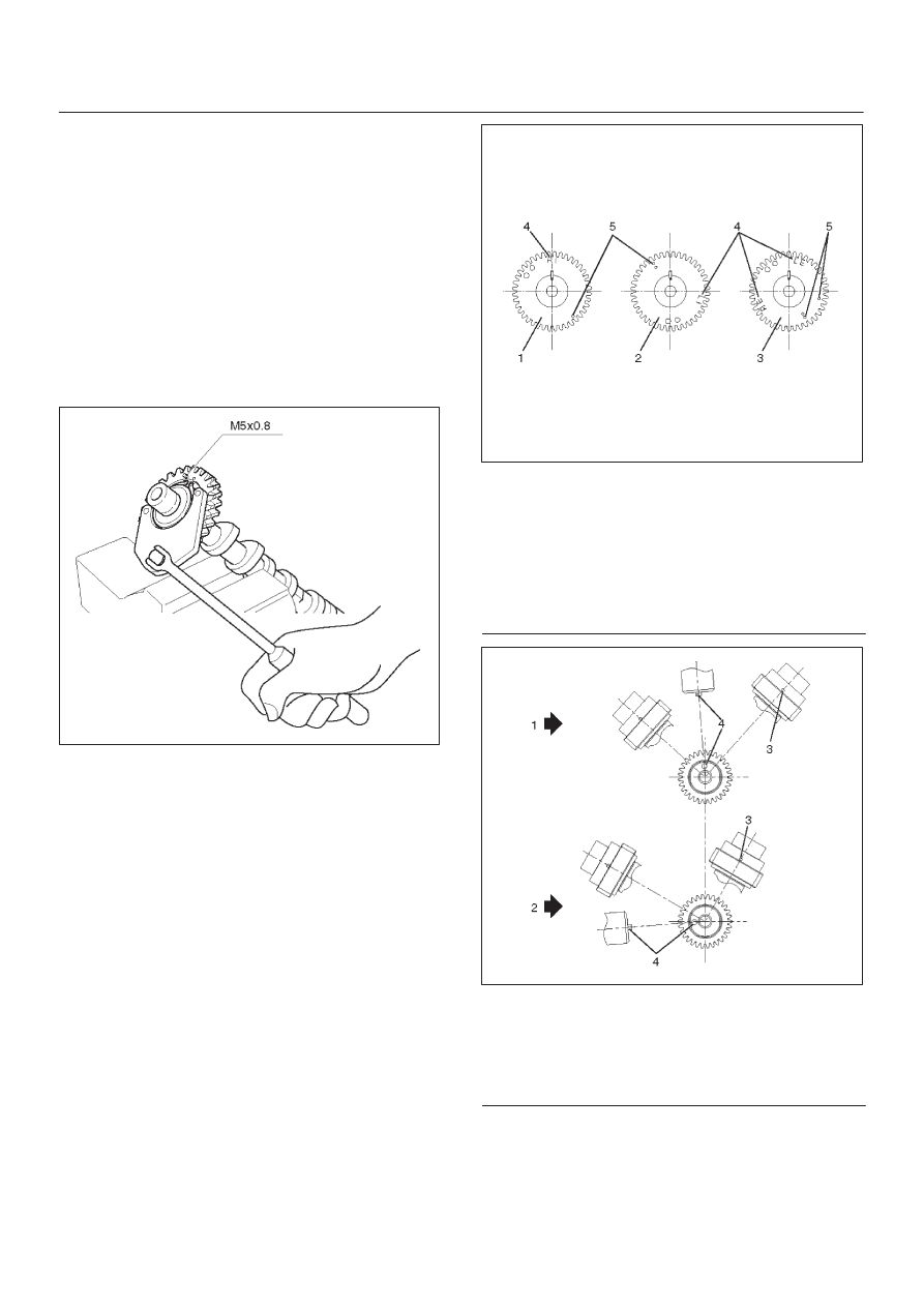
3. Tighten sub gear setting bolt.

1. Use J-42686 to turn sub gear to right direction

until it aligns with the M5 bolt hole between
camshaft driven gear and sub gear.

2. Tighten the M5 bolt to a suitable torque to prevent

the sub gear from moving.

014RW041

4. Install camshaft assembly and camshaft bearing

caps, tighten twenty bolts on one side bank to the
specified torque.
1. Apply engine oil to camshaft journal and bearing

surface of camshaft bearing caps.

2.  Align timing mark on intake camshaft (one dot for

right bank, two dot for left bank) and exhaust
camshaft (one dots for right bank, two dots for left
bank) to timing mark on camshaft drive gear (one
dot).

014RW020

Legend

(1) Intake Camshaft Timing Gear for Right Bank
(2) Intake Camshaft Timing Gear for Left Bank
(3) Exhaust Camshaft Timing Gear
(4) Discrimination Mark

(LI: Left bank intake, RI: Right bank intake)
(LE: Left bank exhaust, RE: Right bank
exhaust)

014RW023

Legend

(1) Right Bank Camshaft Drive Gear
(2) Left Bank Camshaft Drive Gear
(3) Timing Mark on Drive Gear
(4) Dowel Pin

6A–33

ENGINE MECHANICAL (6VD1 3.2L)

014RW024

Legend

(1) Right Bank
(2) Left Bank

(3) Alignment Mark on Camshaft Drive Gear
(4) Alignment Mark on Camshaft
(5) Alignment Mark on Retainer

3. Tighten twenty bolts on numerical order an one

side bank as shown in the illustration.

Torque : 10 N·m (87 lb in)

014RW031

5. Install cylinder head cover RH.

D

Refer to installation procedure for CYLINDER
HEAD COVER RH in this manual.

6. Install cylinder head cover LH.

D

Refer to installation procedure for CYLINDER
HEAD COVER LH in this manual.

7. Install timing belt.

D

Refer to installation procedure for TIMING BELT in
this manual.

8. Install crankshaft pulley.

D

Refer to installation procedure for CRANKSHAFT
PULLEY in this manual.

6A–34

ENGINE MECHANICAL (6VD1 3.2L)

Cylinder Head

Removal

1. Remove engine hood.
2. Disconnect battery ground cable.
3. Drain radiator coolant.
4. Drain engine oil.
5. Remove crankshaft pulley.

D

Refer to removal procedure for Crankshaft Pulley in
this manual.

6. Remove timing belt.

D

Refer to removal procedure for Timing Belt in this
manual.

7. Remove cylinder head cover LH.

D

Refer to removal procedure for Cylinder Head
Cover LH in this manual.

8. Remove cylinder head cover RH.

D

Refer to removal procedure for Cylinder Head
Cover RH in this manual.

9. Remove common chamber.

D

Refer to removal procedure for Common Chamber
in this manual.

10. Remove cylinder head assembly.

1. Loosen head bolts in reverse of tightening

sequence.

2. Remove cylinder head assembly.

014RW028

Legend

(1) Cylinder Head
(2) Cylinder Head Bolt
(3) Camshaft

Installation

1. Install cylinder head assembly to cylinder block.

A. Put cylinder head gasket on the cylinder block.

NOTE: There is discrimination mark “R” for right bank
and “L” for left bank on the cylinder head gasket as shown
in the illustration.
Do not reuse cylinder head gasket.

011RW005

B. Align dowel pin hole to dowel pin on the cylinder

block.

C. Position cylinder head on the cylinder bolock.
D. Tighten two bolts temporarily by hand to prevent

the cylinder head assembly from moving.

E. Using J-24239-01 cylinder head bolt wrench,

tighten bolts in numerical order as shown in the
illustration to the specified torque.

6A–35

ENGINE MECHANICAL (6VD1 3.2L)

NOTE: Do not reuse cylinder head bolts.
Do not apply any lubricant to the cylinder head bolts.

Torque :
Temporary : 29 N·m (22 lb ft)
Final : 64 N·m (47 lb ft)

014RW029

2. Install common chamber.

D

Refer to installation procedure for Common
Chamber in this manual.

3. Install cylinder head cover RH.

D

Refer to installation procedure for Cylinder Head
Cover RH in this manual.

4. Install cylinder head cover LH.

D

Refer to installation procedure for Cylinder Head
Cover LH in this manual.

5. Install timing belt.

D

Refer to installation procedure for Timing Belt in this
manual.

6. Install crankshaft pulley.

D

Refer to installation procedure for Crankshaft
Pulley in this manual.


Content   ..  1355  1356  1357  1358   ..