Isuzu Amigo / Axiom / Trooper / Rodeo / VehiCross. Manual - part 127


  Index      Isuzu     Isuzu Amigo / Axiom / Trooper / Rodeo / VehiCross - service repair manual 1999-2002 year


Search            


Content   ..  125  126  127  128   ..


Isuzu Amigo / Axiom / Trooper / Rodeo / VehiCross. Manual - part 127


4C–8

DRIVE SHAFT SYSTEM

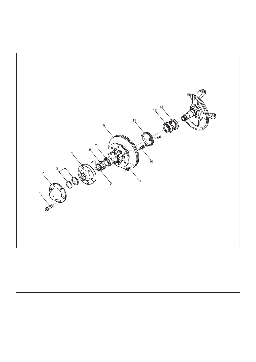
Front Hub and Disc (4WD Model)

Disassembled View

411RW001

Legend

(1) Bolt
(2) Cap
(3) Snap Ring and Shim
(4) Hub Flange
(5) Lock Washer and Lock Screw
(6) Hub Nut

(7) Outer Bearing
(8) Bolt
(9) Hub and Disc Assembly

(10) Wheel Pin

(11) ABS Sensor Ring

(12) Inner Bearing
(13) Oil Seal

Disassembly

1. Before disassembly, select the 2WD position with the

4WD switch.

2. Jack up the front of vehicle and support frame with

jack attached.

3. Remove the two bolts from the rear side of the

knuckle arm, then remove the brake caliper, with the
brake hose attached.
Use a wire to attach the brake caliper to the upper link.
Refer to 

Disk Brakes in Brake section.

4. Remove Bolt.
5. Remove cap.

4C–9

DRIVE SHAFT SYSTEM

6. Remove snap ring and shim.
7. Remove hub flange.
8. Remove lock washer and lock screw.
9. Remove hub nut, using front hub nut wrench

J–36827.

901RW054

10. Remove hub and disc assembly.

11. Remove ABS sensor ring.

12. Remove outer bearing.
13. Remove oil seal.
14. Remove inner bearing.
15. Use a brass bar to remove the outer bearing outer

race(1), oil seal, inner bearing and inner bearing outer
race(2) from the hub.

411RS002

16. Remove bolt.

If necessary, replace the wheel pin in the following
manner.

D

Scribe mark(1) on the hub to disc before
disassembly to insure proper assembly.

D

Clamp the hub and disc assembly in a vise, using
protective pads. Remove the 6 disc–to–hub
retaining bolts.

411RS003

D

Place hub on a suitable work surface and remove
wheel studs, as required, by using a hammer.

411RS004

4C–10

DRIVE SHAFT SYSTEM

Inspection and Repair

Make necessary correction or parts replacement if wear,
damage, corrosion or any other abnormal condition are
found through inspection.
Check the following parts.

D

Hub

D

Hub bearing, oil seal

D

Knuckle spindle

D

Disc

D

Caliper

D

Shift on the fly system parts (Cap, Hub flange, Shim,
Snap ring)

D

ABS sensor ring

For inspection and servicing of disc caliper and related
parts, refer to 

Disc Brakes in Brake section.

Reassembly

1. Install wheel pin.

D

Place the hub on a wood workbench or a block of
wood approx. 6” by 6” to protect the wheel stud
ends and threads.

D

Insert a wheel stud using a hammer.

NOTE: Be sure the wheel stud is started squarely and
seats completely.

411RS005

2. Align scribe marks(1) and attach the hub to the disc,

then tighten the bolts to the specified torque.

Torque: 103 N·m (76 lb ft)

411RS003

3. Install inner bearing.

Install the outer race by driving it into the hub by using
insatller J–36829 and grip J–8092.

901RW055

4C–11

DRIVE SHAFT SYSTEM

4. Install outer bearing.

Install the outer race by driving it into the hub by using
install J–36828 and grip J–8092.

901RW056

5. Install oil seal by using installer J–36830 and grip

J–8092.
Apply Multipurpose grease (NLGI No.2 or equivalent)
to the lip portion.

901RW057

6. Install ABS sensor ring, then tighten the bolts to the

specified torque.

Torque: 18 N·m (13 lb ft)

7. Install hub and disc assembly.

D

Apply grease in the hub.

D

Apply wheel bearing type grease NLGI No. 2 or
equivalent to the outer and inner bearing.

Grease Amount

Hub

35 g (1.23 oz)

Outer bearing

10 g (0.35 oz)

Inner bearing

15 g (0.53 oz)

411RS009

Legend

(1) Inner Bearing
(2) Hub
(3) Outer Bearing

8. Install hub nut.

Turn to the place where there is a chamfer in the
tapped hole to the outer side, then attach the nut by
using front hub nut wrench J–36827.

901RW054


Content   ..  125  126  127  128   ..