Isuzu Amigo / Axiom / Trooper / Rodeo / VehiCross. Manual - part 126


  Index      Isuzu     Isuzu Amigo / Axiom / Trooper / Rodeo / VehiCross - service repair manual 1999-2002 year


Search            


Content   ..  124  125  126  127   ..


Isuzu Amigo / Axiom / Trooper / Rodeo / VehiCross. Manual - part 126


4C–4

DRIVE SHAFT SYSTEM

7. Remove hub and disc assembly.
8. Remove ABS sensor ring.
9. Remove outer bearing.

10. Remove oil seal.

11. Remove inner bearing.

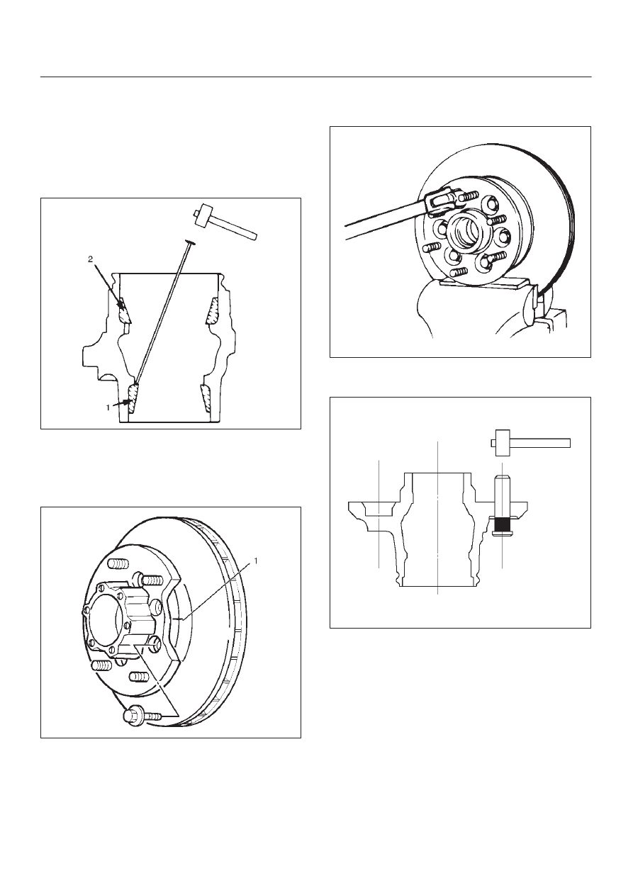
12. Use a brass bar to remove the outer bearing outer

race(1), oil seal, inner bearing and inner bearing outer
race(2) from the hub.

411RS002

13. Remove bolt.
14. If necessary, replace the wheel pin in the following

manner.

D

Scribe mark(1) on hub to disc before disassembly
to insure proper assembly.

411RS003

D

Clamp hub and disc assembly in vise, using
protective pads.  Remove six(6) disc-to-hub
retaining bolts.

411RS021

D

Place hub on a suitable work surface and remove
wheel studs, as required, using a hammer.

411RS004

Inspection and Repair

Make necessary correction or parts replacement if wear,
damage, corrosion or any other abnormal condition are
found through inspection.
Check the following parts.

D

Hub

D

Hub bearing oil seal

D

Knuckle spindle

D

Disc

D

Caliper

D

ABS sensor ring

For inspection and servicing of disc caliper and related
parts, refer to 

Disc Brake in Brake section.

4C–5

DRIVE SHAFT SYSTEM

Reassembly

1. Install wheel pin. 

D

Place hub on a wood workbench or a block of wood
approx.  6” by 6” to protect the wheel stud ends and
threads.

D

Install wheel stud, using a hammer.

NOTE: Be sure wheel stud is started squarely and seats
completely.

411RS005

2. Align scribe marks(1) and attach the  hub to disc then

tighten the bolts to the specified torque.

Torque: 103 N·m (76 lb ft)

411RS003

3. Install inner bearing.

Install the outer race by driving it into the hub by using
installer J–36829 and grip J–8092.

411RS023

4. Install outer bearing.

Install the outer race by driving it into the hub by using
installer J–36828 and grip J-8092.

901RW056

4C–6

DRIVE SHAFT SYSTEM

5. Install oil seal by using installer J–36830 and grip

J–8092.
Apply Multipurpose grease (NLGI No. 2 or equivalent)
to the lip portion.

901RW057

6. Inatall ABS sensor ring, then tigthen the bolts to the

specified torque.

Torque: 18 N·m (13 lb ft)

7. Install hub and disc assembly.

D

Apply grease in the hub.

D

Apply wheel bearing type grease (NLGI No.2 or
equivalent) to the outer and inner bearing.

Hub

35 g (1.23 oz)

Outer bearing

10 g (0.35 oz)

Inner bearing

15 g (0.53 oz)

8. Install hub nut.

Turn the place where there is a chamfer in the tapped
hole to the outer side, then attach the nut by using
front hub nut wrench J–36827.

901RW054

Preload Adjustment

1. Tighten the hub nut to 29.4 N·m (21.7 lb ft), then

fully loosen the nut.

2. Tighten the hub nut to the value given below,

using a spring scale on the wheel pin.

Bearing Preload

New bearing and New
oil seal

19.6 – 24.5 N

(4.4 – 5.5 lb)

Used bearing and New
oil seal

11.8 – 17.7 N

(2.6 – 4.0 lb)

If the measured bearing preload is outside the
specifications, adjust it by loosening or tightening
the hub nut.

411RS011

4C–7

DRIVE SHAFT SYSTEM

9. Install lock washer and lock screw.

D

Turn the side with larger diameter of the tapered
bore to the vehicle outer side, then attach the
washer.

D

If the bolt holes in the lock plate are not aligned with
the corresponding holes in the nut, reverse the lock
plate.

D

If the bolt holes are still out of alignment, turn in the
nut just enough to obtain alignment.

D

Screw is to be fastened tightly so its head may
come lower than the surface of the washer.

411RS012

10. Install cover and gasket then tighten the cover bolt.

Torque: 59 N·m (43 lb ft)

11. Install brake caliper and tighten fixing bolt.


Content   ..  124  125  126  127   ..