Isuzu Amigo / Axiom / Trooper / Rodeo / VehiCross. Manual - part 119
DRIVE LINE CONTROL SYSTEM (TOD)
4B2–94
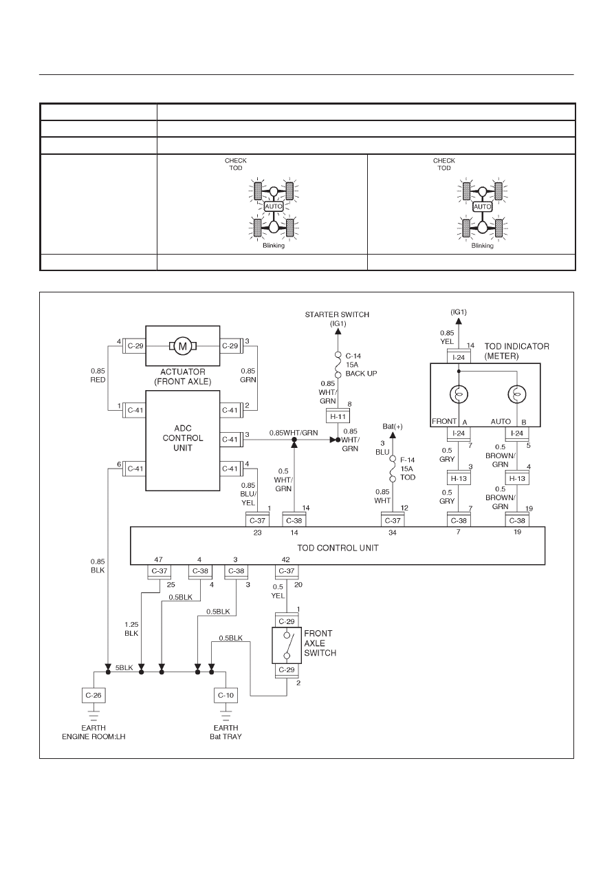
Chart E–1
AXLE switch circuit wires are broken.
Function of circuit
—
Fail condition
Both the TOD and 4L modes are disabled. (The transition status is not removed.)
Indicator lamp state
TOD switch position
TOD
4L
D04R200023