Isuzu Amigo / Axiom / Trooper / Rodeo / VehiCross. Manual - part 117


  Index      Isuzu     Isuzu Amigo / Axiom / Trooper / Rodeo / VehiCross - service repair manual 1999-2002 year


Search            


Content   ..  115  116  117  118   ..


Isuzu Amigo / Axiom / Trooper / Rodeo / VehiCross. Manual - part 117


DRIVE LINE CONTROL SYSTEM (TOD)

4B2–86

Chart D–1

4L switch circuit wires are broken or the battery circuit is short-circuited.

Function of circuit

Fail condition

When the TOD switch is changed to the 4L position, the indicator 4L mode goes on and

off.

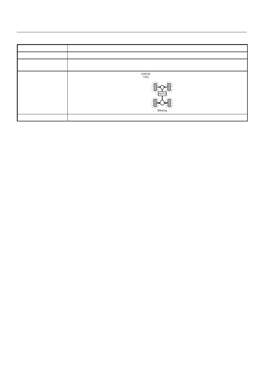
Indicator lamp state

TOD switch position

4L

4B2–87

DRIVE LINE CONTROL SYSTEM (TOD)

D04R200022

DRIVE LINE CONTROL SYSTEM (TOD)

4B2–88

Step

Action

Yes

No

1

1. Turn on the starter switch.
2. The car stops, the AT selector is the N position, and the brake

is applied.

When the TOD switch is changed to the TOD (or 2H) position, is
12V observed between terminals 44 and 47 (4L switch)?

Go to 

Step 2

Go to 

Step 4

2

1. The car stops, the AT selector is the N position, and the brake

is applied.

When the TOD switch is changed to the 4L position, does the
transfer become the 4L state?

Go to 

Step 3

Refer to

“Diagnosis from

symptom”.

3

Is 0V observed between the terminal 44 and 47?

The ECU has

failed.Replace

the ECU.

Go to 

Step 10

Go to 

Step 10

4

1. The car stops, the AT selector is the N position, and the brake

is applied.

When the TOD switch is changed to the TOD (or 2H) position, is
12V observed between the connector (C–37) terminal 22 and 25?

Go to 

Step 5

Go to 

Step 6

5

1. Turn off the starter switch and connect the EUC connector.
2. The car stops, the AT selector is the N position, and the brake

is applied.

When the TOD switch is changed to the 4L position, is 0V
observed between terminals (C–37) 22 and (C–37) 25 (4L
switch)?

The phenomenon

is not

reproduced.

Refer to 

“Trouble

intermittently

observed”.

Go to 

Step 6

6

1. Turn off the starter switch and connect ECU connector.
2. Turn on the starter switch.
3. The car stops, the AT selector is the N position, and the brake

is applied.

4. Change the TOD switch to the TOD (or 2H) position.
5. After the transfer has changed to the TOD (or 2H) mode, turn

off the starter switch and disconnect the ECU connector
(C–37).

Is there the continuity between the connector (C–37) terminal 22
and 25?

Go to 

Step 9

Go to 

Step 7

7

1. Turn off the starter switch and connect the ECU connector.
2. Turn on the starter switch.
3. The car stops, the AT selector is the N position, and the brake

is applied.

4. Change the TOD switch to the 4L position.
5. After the transfer has changed to the 4L mode, turn off the

starter switch.

6. Disconnect the ECU connector.

Is there the continuity between the connector (C–37) terminal 22
and 25?

The phenomenon

is not

reproduced.

Refer to 

“Trouble

intermittently

observed”.

Go to 

Step 8

8

1. Turn off the starter switch and connect the ECU connector.
2. Turn on the starter switch.
3. The car stops, the AT selector is the N position, and the brake

is applied.

4. Change the TOD switch to the TOD (or 2H) position.
5. After the transfer has changed to the TOD (or 2H) mode, turn

off the starter switch.

6. Disconnect the transfer connector (A–1).

Is there the continuity between the connector terminal (A–1) 12
and GND?

Repair the

transfer.

Go to 

Step 10

Repair the circuit

between (C–37)

22 and (A–1) 12.

Go to 

Step 10

4B2–89

DRIVE LINE CONTROL SYSTEM (TOD)

Step

No

Yes

Action

9

1. Turn off the starter switch and connect the connector (A–1).
2. Turn on the starter switch.
3. The car stops, the AT selector is N position, and the brake is

applied.

4. Change the TOD switch to the 4L position.
5. After the transfer has changed to the 4L mode, turn off the

starter switch.

6. Disconnect the transfer connector (A–1).

Is there the continuity between the connector terminal (A–1) 12
and GND?

Repair the circuit

between

(C–37)22 and

(A–1)12.

Go to 

Step 10

Repair the

transfer.

Go to 

Step 10

10

Check that all the parts are mounted.

Is this step complete?

Verify the repair.

Go to 

Step 10


Content   ..  115  116  117  118   ..