Isuzu Amigo / Axiom / Trooper / Rodeo / VehiCross. Manual - part 1183


  Index      Isuzu     Isuzu Amigo / Axiom / Trooper / Rodeo / VehiCross - service repair manual 1999-2002 year


Search            


Content   ..  1181  1182  1183  1184   ..


Isuzu Amigo / Axiom / Trooper / Rodeo / VehiCross. Manual - part 1183


5B–4

ANTI-LOCK BRAKE SYSTEM

Front Wheel Speed Sensor

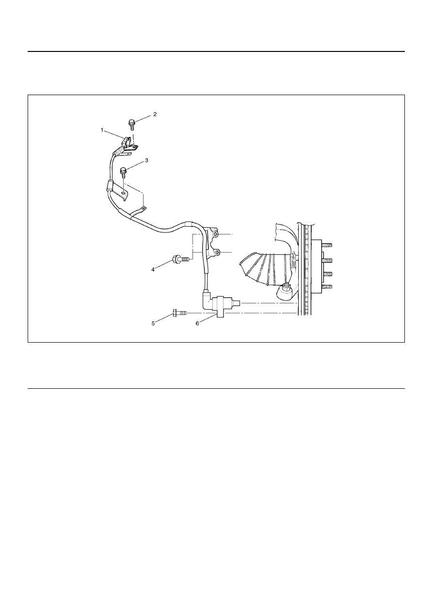
Front Wheel Speed Sensor and Associated Parts

350R200004

EndOFCallout

Removal

1. Remove speed sensor connector.

2. Remove sensor cable fixing bolt (Upper side).

3. Remove sensor cable fixing bolt (Lower side).

4. Remove the speed sensor cable fixing bolt.

5. Remove speed sensor.

Inspection and Repair

1. Check the speed sensor pole piece for presence of

foreign materials; remove any dirt, etc.

2. Check the pole piece for damage; replace speed

sensor if necessary.

3. Check the speed sensor cable for short or open

circuit, and replace with a new one if necessary.
To check for cable short or open, bend or stretch the
cable while checking for continuity.

4. Check the sensor ring for damage including tooth

chipping, and if damaged, replace the sensor ring
assembly. Refer to removal of the sensor ring in
Section 4C “Front hub and disc”.

5. On 2WD vehicles, the hub unit bearing and front

wheel speed sensor are a single unit.
Check the outside of the unit for damage. If there is
damage, refer to Front hub and disc in Section 4C of
this Manual.
The hub unit bearing and front wheel speed sensor
cannot be disassembled. They must be replaced as
a complete unit.

Legend

(1) Speed Sensor Connector
(2) Sensor Cable Fixing Bolt (Frame side)
(3) Sensor Cable Fixing Bolt (Upper Arm side)

(4) Sensor Cable Fixing Bolt (Knuckle side)
(5) Sensor Fixing Bolt
(6) Speed Sensor

ANTI-LOCK BRAKE SYSTEM

5B–5

Installation

1. Install speed sensor and take care not to hit the

speed sensor pole during installation.

2. Install speed sensor fixing bolt and tighten the fixing

bolt to the specified torque.

Torque: 11 N·m (95 lb in)

3. Install speed sensor cable fixing bolt (Lower side)

and tighten the fixing bolt to the specified torque.

Torque : 24 N·m (17 lb ft)

4. Install speed sensor cable fixing bolt (Upper side)

and tighten the fixing bolt to the specified torque.

Torque : 6 N·m (52 lb in)

NOTE:  Confirm that a white line marked on the cable is
not twisted when connecting the speed sensor cable.

5. Install speed sensor connector.

Rear Wheel Speed Sensor

Removal

1. Disconnect harness connector (1).

2. Remove sensor fixing bolt (2) .

3. Remove speed sensor (3).

350R100004

Inspection and Repair

1. Check speed sensor pole for presence of foreign

materials; remove any dirt, etc.

2. Check the pole for damage, and replace speed

sensor if necessary.

3. Check speed sensor cable for short or open, and

replace with a new one if necessary.     To check for
cable short or open, bend or stretch the cable while
checking for continuity.

4. Check the sensor ring for damage including tooth

chipping, and if damaged, replace the axle shaft
assembly.     Refer to removal of the sensor ring in
Section 4A2 Differential (Rear).

Installation

1. Install speed sensor (3).

2. Tighten the sensor fixing bolt (2) to the specified

torque.

Torque : 24 N·m (17 lb ft)

3. Connect harness connector (1).

350R100004

POWER-ASSISTED BRAKE SYSTEM

5C–1

RODEO

BRAKES

CONTENTS

POWER-ASSISTED BRAKE SYSTEM

Service Precaution. . . . . . . . . . . . . . . . . . . . .

5C–2

General Description . . . . . . . . . . . . . . . . . . . .

5C–2

Diagnosis . . . . . . . . . . . . . . . . . . . . . . . . . . . .

5C–6

General Diagnosis . . . . . . . . . . . . . . . . . . . . .

5C–7

Hydraulic Brakes . . . . . . . . . . . . . . . . . . . . . .

5C–10

Filling Master Cylinder Reservoir . . . . . . . .

5C–10

Deterioration of Brake Fluid  . . . . . . . . . . . .

5C–10

Leakage of Brake Fluid. . . . . . . . . . . . . . . .

5C–10

Bleeding Brake Hydraulic System  . . . . . . .

5C–10

Flushing Brake Hydraulic System. . . . . . . .

5C–11

Brake Pipes and Hoses  . . . . . . . . . . . . . . .

5C–11

Brake Hose Inspection . . . . . . . . . . . . . . . .

5C–12

Front Caliper Brake Hose  . . . . . . . . . . . . . . .

5C–12

Front Caliper Brake Hose and Associated

Parts . . . . . . . . . . . . . . . . . . . . . . . . . . . . . .

5C–12

Removal . . . . . . . . . . . . . . . . . . . . . . . . . . .

5C–12

Installation  . . . . . . . . . . . . . . . . . . . . . . . . .

5C–12

Rear Axle Brake Hose . . . . . . . . . . . . . . . . . .

5C–13

Rear Axle Brake Hose and Associated Parts

5C–13

Removal . . . . . . . . . . . . . . . . . . . . . . . . . . .

5C–13

Installation  . . . . . . . . . . . . . . . . . . . . . . . . .

5C–13

Brake Pipe . . . . . . . . . . . . . . . . . . . . . . . . . . .

5C–14

Removal . . . . . . . . . . . . . . . . . . . . . . . . . . .

5C–14

Installation  . . . . . . . . . . . . . . . . . . . . . . . . .

5C–14

P & B (Proportioning and Bypass) Valve . . . .

5C–15

P & B (Proportioning and Bypass) Valve

Sectional View . . . . . . . . . . . . . . . . . . . . . .

5C–15

Removal . . . . . . . . . . . . . . . . . . . . . . . . . . .

5C–15

Installation  . . . . . . . . . . . . . . . . . . . . . . . . .

5C–15

Main Data and Specifications . . . . . . . . . . .

5C–16

Brake Pedal . . . . . . . . . . . . . . . . . . . . . . . . . .

5C–17

Checking Pedal Height . . . . . . . . . . . . . . . .

5C–17

Checking Pedal Travel . . . . . . . . . . . . . . . .

5C–17

Brake Pedal and Associated Parts . . . . . . .

5C–18

Removal . . . . . . . . . . . . . . . . . . . . . . . . . . .

5C–18

Installation  . . . . . . . . . . . . . . . . . . . . . . . . .

5C–18

Stoplight Switch . . . . . . . . . . . . . . . . . . . . . . .

5C–19

Parts Location. . . . . . . . . . . . . . . . . . . . . . .

5C–19

Removal . . . . . . . . . . . . . . . . . . . . . . . . . . .

5C–19

Installation  . . . . . . . . . . . . . . . . . . . . . . . . .

5C–19

Main Data and Specifications . . . . . . . . . . .

5C–20

Master Cylinder Assembly . . . . . . . . . . . . . . .

5C–21

Master Cylinder Assembly and Associated

Parts . . . . . . . . . . . . . . . . . . . . . . . . . . . . . .

5C–21

Removal . . . . . . . . . . . . . . . . . . . . . . . . . . .

5C–21

Inspection . . . . . . . . . . . . . . . . . . . . . . . . . .

5C–21

Master Cylinder Assembly . . . . . . . . . . . . . . .

5C–22

Master Cylinder Assembly Desassembled

View . . . . . . . . . . . . . . . . . . . . . . . . . . . . . .

5C–22

Desassembly  . . . . . . . . . . . . . . . . . . . . . . .

5C–22

Inspection . . . . . . . . . . . . . . . . . . . . . . . . . .

5C–22

Reassembly  . . . . . . . . . . . . . . . . . . . . . . . .

5C–23

Installation. . . . . . . . . . . . . . . . . . . . . . . . . .

5C–23

Main Data and Specifications  . . . . . . . . . . . .

5C–24

Vacuum Booster Assembly . . . . . . . . . . . . . .

5C–25

Vacuum Booster Assembly and Associated

Parts . . . . . . . . . . . . . . . . . . . . . . . . . . . . . .

5C–25

Removal . . . . . . . . . . . . . . . . . . . . . . . . . . .

5C–25

Inspection and Repair. . . . . . . . . . . . . . . . .

5C–26

Exterior Components . . . . . . . . . . . . . . . . . . .

5C–27

Exterior Components and Associated Parts

5C–27

Removal . . . . . . . . . . . . . . . . . . . . . . . . . . .

5C–27

Inspection and Repair. . . . . . . . . . . . . . . . .

5C–28

Installation. . . . . . . . . . . . . . . . . . . . . . . . . .

5C–28

Vacuum Booster Overhaul. . . . . . . . . . . . . . .

5C–28

Vacuum Booster . . . . . . . . . . . . . . . . . . . . .

5C–28

Main Data and Specifications . . . . . . . . . . .

5C–29

Front Disc Brake Pads . . . . . . . . . . . . . . . . . .

5C–30

Front Disc Brake Pads Inspection  . . . . . . .

5C–30

Front Disc Brake Pads and Associated Parts

5C–30

Removal . . . . . . . . . . . . . . . . . . . . . . . . . . .

5C–31

Installation. . . . . . . . . . . . . . . . . . . . . . . . . .

5C–31

Front Disc Brake Rotor  . . . . . . . . . . . . . . . . .

5C–33

Inspection . . . . . . . . . . . . . . . . . . . . . . . . . .

5C–33

Replacing Brake Rotors  . . . . . . . . . . . . . . .

5C–33

Refinishing Brake Rotors  . . . . . . . . . . . . . .

5C–33

Front Disc Brake Caliper Assembly . . . . . . . .

5C–35

Front Disc Brake Caliper Assembly and

Associated Parts  . . . . . . . . . . . . . . . . . . . .

5C–35

Removal . . . . . . . . . . . . . . . . . . . . . . . . . . .

5C–35

Installation. . . . . . . . . . . . . . . . . . . . . . . . . .

5C–36

Front Disc Brake Caliper . . . . . . . . . . . . . . . .

5C–38

Front Disc Brake Caliper Disassembled View

5C–38

Disassembly . . . . . . . . . . . . . . . . . . . . . . . .

5C–38

Inspection and Repair. . . . . . . . . . . . . . . . .

5C–39

Reassembly  . . . . . . . . . . . . . . . . . . . . . . . .

5C–39

Main Data and Specifications . . . . . . . . . . .

5C–40

Rear Disc Brake Pads (4

´4 Model) . . . . . . . .

5C–41

Brake Pads Inspection . . . . . . . . . . . . . . . .

5C–41

Brake Pads and Associated Parts  . . . . . . .

5C–41

Removal . . . . . . . . . . . . . . . . . . . . . . . . . . .

5C–42

Installation. . . . . . . . . . . . . . . . . . . . . . . . . .

5C–42

Rear Disc Brake Rotor (4

´4 Model). . . . . . . .

5C–44

Inspection . . . . . . . . . . . . . . . . . . . . . . . . . .

5C–44

Replacing Brake Rotors  . . . . . . . . . . . . . . .

5C–44

Refinishing Brake Rotors  . . . . . . . . . . . . . .

5C–44

Rear Drum (In Disc) Inside Diameter Check

5C–45

Rear Disc Brake Caliper Assembly

SECTION

5C–2

POWER-ASSISTED BRAKE SYSTEM

(4

´4 Model) . . . . . . . . . . . . . . . . . . . . . . . . .

5C–46

Rear Disc Brake Caliper Assembly and

Associated Parts  . . . . . . . . . . . . . . . . . . . .

5C–46

Removal . . . . . . . . . . . . . . . . . . . . . . . . . . .

5C–46

Installation  . . . . . . . . . . . . . . . . . . . . . . . . .

5C–47

Rear Disc Brake Caliper (4

´4 Model) . . . . . .

5C–48

Rear Disc Brake Caliper Disassembled View

5C–48

Disassembly . . . . . . . . . . . . . . . . . . . . . . . .

5C–49

Inspection and Repair. . . . . . . . . . . . . . . . .

5C–49

Reassembly  . . . . . . . . . . . . . . . . . . . . . . . .

5C–49

Main Data and Specifications (4

´4 Model).

5C–51

Brake Lining. . . . . . . . . . . . . . . . . . . . . . . . . .

5C–52

Brake Lining and Associated Parts . . . . . . .

5C–52

Removal . . . . . . . . . . . . . . . . . . . . . . . . . . .

5C–52

Brake Lining Inspection  . . . . . . . . . . . . . . .

5C–53

Installation. . . . . . . . . . . . . . . . . . . . . . . . . .

5C–53

Drum Brake Adjustment (4

´2 Model) . . . . .

5C–54

Servicing The Brake Drum . . . . . . . . . . . . .

5C–54

Wheel Cylinder Assembly (4

´2 Model) . . . . .

5C–55

Wheel Cylinder Assembly and Associated

Parts . . . . . . . . . . . . . . . . . . . . . . . . . . . . . .

5C–55

Removal . . . . . . . . . . . . . . . . . . . . . . . . . . .

5C–55

Installation. . . . . . . . . . . . . . . . . . . . . . . . . .

5C–55

Disassembled View  . . . . . . . . . . . . . . . . . .

5C–56

Disassembly . . . . . . . . . . . . . . . . . . . . . . . .

5C–56

Inspection and Repair. . . . . . . . . . . . . . . . .

5C–56

Reassembly  . . . . . . . . . . . . . . . . . . . . . . . .

5C–56

Main Data and Specifications  . . . . . . . . . . . .

5C–58

Service Precaution

WARNING:  THIS VEHICLE HAS A SUPPLEMENTAL
RESTRAINT SYSTEM (SRS).   REFER TO THE SRS
COMPONENT AND WIRING LOCATION VIEW IN
ORDER TO DETERMINE WHETHER   YOU ARE
PERFORMING SERVICE ON OR NEAR THE SRS
COMPONENTS OR THE SRS WIRING.   WHEN YOU
ARE PERFORMING SERVICE ON OR NEAR THE
SRS COMPONENTS OR THE SRS WIRING,   REFER
TO THE SRS SERVICE INFORMATION. FAILURE TO
FOLLOW WARNINGS COULD RESULT   IN
POSSIBLE AIR BAG DEPLOYMENT, PERSONAL
INJURY, OR OTHERWISE UNNEEDED SRS SYSTEM
REPAIRS.

CAUTION:  Always use the correct fastener in the
proper location.   When you replace a fastener, use
ONLY the exact part number for that application.
ISUZU will   call out those fasteners that require a
replacement after removal. ISUZU will also call out
the   fasteners that require thread lockers or thread
sealant. UNLESS OTHERWISE SPECIFIED, do   not
use supplemental coatings (Paints, greases, or
other corrosion inhibitors) on threaded   fasteners
or fastener joint interfaces. Generally, such
coatings adversely affect the fastener   torque and
the joint clamping force, and may damage the
fastener. When you install fasteners,   use the
correct tightening sequence and specifications.
Following these instructions can help you   avoid
damage to parts and systems.

General Description

Master Cylinder Assembly

330R200002


Content   ..  1181  1182  1183  1184   ..