Isuzu Amigo / Axiom / Trooper / Rodeo / VehiCross. Manual - part 1155


  Index      Isuzu     Isuzu Amigo / Axiom / Trooper / Rodeo / VehiCross - service repair manual 1999-2002 year


Search            


Content   ..  1153  1154  1155  1156   ..


Isuzu Amigo / Axiom / Trooper / Rodeo / VehiCross. Manual - part 1155


4C–32

DRIVE SHAFT SYSTEM

2. Set the yoke in the arbor press with a piece of tube

stock beneath it.
Place a solid plug on the upper bearing assembly
and press it through to release the lower bearing
assembly.

401RW020

3. If the bearing assembly will not pull out by hand

after pressing, tap the base of the lug near the
bearing assembly to dislodge it.

4. To remove the opposite bearing, turn the yoke over

and straighten the spider in the open hole.  Then
carefully press on the end of the spider so the
remaining bearing moves straight out of the bearing
spider hole.  If the spider or bearing are cocked, the
bearing will score the walls of the spider hole and
ruin the yoke. 

5. Repeat this procedure on the remaining bearing to

remove the spider from the yoke.

6. Make sure of proper position for reinstallation by

applying setting marks, then remove spider .

Inspection and Repair

Make necessary correction or parts replacement if wear,
damage, corrosion or any other abnormal condition is
found through inspection.

NOTE:  When any part of the journal assembly (spider,
needle roller bearing) requires replacement, be sure to
replace the entire assembly.
Check the following parts for wear, damage, noise or
any other abnormal conditions.

1. Spider

2. Needle roller bearing

3. Yoke

4. Flange

5. Boot

Spider pin for wear

Spider pin should be smooth and free from fretting or
galling.  Visible signs of needle presence is normal, but
wear should not be felt.

401RW038

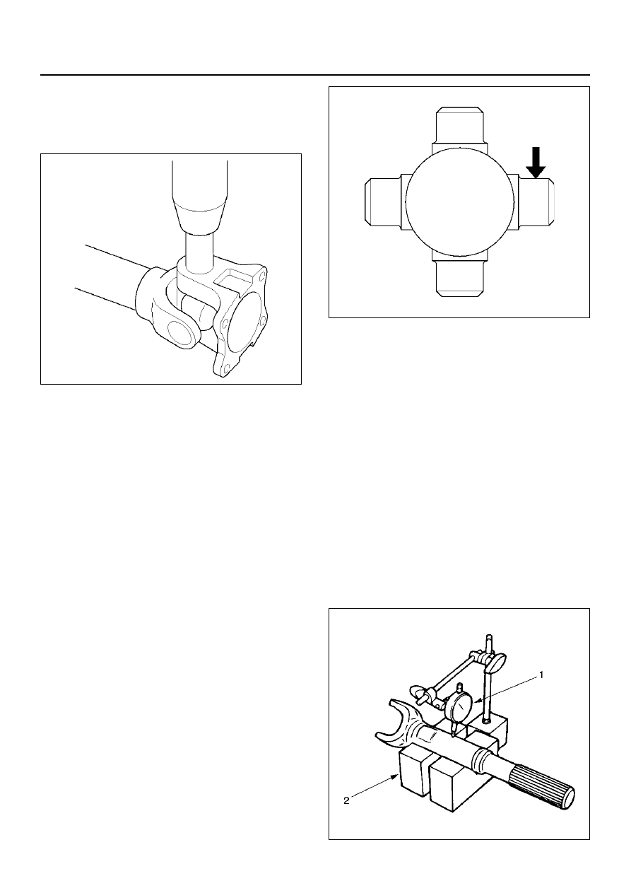
Propeller shaft run–out

Support the propeller shaft on V-blocks (2) and check
for run-out by holding the probe of a dial indicator (1) in
contact with the shaft.

Static run-out limit:

0.13 mm  (0.005in)

TIR on the neck of the slip tube shaft (with a
boot).

0.25 mm  (0.010in)

TIR on the ends of the tubing 3 inch from the
welds.

0.38 mm  (0.015in)

TIR at the linear center of the tube.

0.38 mm  (0.015in)

TIR for the full length of tube with 30" or less of
tubing.

(TIR : Total Indicator Reading)

401RS027

DRIVE SHAFT SYSTEM

4C–33

Spline

The nylon-coated spline should be free from nicks and
dings and the underlying steel spline should not be
visible.
After cleaning the nylon coating spline, the coating
should exhibit only slight indicator of wear.
Grease volume is approximately 10 grams of grease in
total.  Grease should be evenly applied to both the
female and  the male slip splines using a small brush.
After assembly of the slip joint, the sliding joint should
be fully worked from the full collapsed to the full
extended position.

Play in the universal joint

Limit:Less  than 0.15 mm (0.006in)

401RW023

Preload of the universal joint

Preload should be 0 to 49 N(0 to11.0 lb).  Joints should
rotate smoothly and freely and should exhibit no rough
or ratchety movement.

401RW019

Universal Joint Reassembly

1. Install spider to flange yoke. Be sure to install the

spider by aligning the setting marks made during
disassembly.

2. Pack the four grease cavities of the spider with a

high quality, extreme pressure N.L.G.I. Grade 2
grease.  Do not add additional grease to the bearing
cup assembly.

3. Move one end of the spider to cause a trunnion to

project through the spider hole beyond the outer
machined face of the yoke lug.  Place a bearing
over the trunnion diameter and align it to the spider
hole.  Using an arbor press, hold the trunnion in
alignment with the spider hole and place a solid plug
on the upper bearing.  Press the bearing into the
spider hole enough to install a snap ring.

401RW020

4. Install a snap ring.

Be sure the snap rings are properly seated in the
grooves.

5. Repeat steps 3 and 4 to install the opposite bearing.

If the joint is stiff, strike the yoke ears with a soft
hammer to seat needle bearings.

4C–34

DRIVE SHAFT SYSTEM

6. Align setting marks (1) and join the yokes.

401RW018

7. Install snap ring.

Reassembly

401RW032

EndOFCallout

Legend

(1) Sleeve Yoke
(2) Clamp

(3) Boot
(4) Clamp
(5) Tube Assembly

DRIVE SHAFT SYSTEM

4C–35

1. Apply grease evenly to both the female and male

splines.

2. Apply a small amount of grease by finger to the

outer lips of the boot.

3. Slide the boot onto the yoke shaft being careful not

to damage the spline coating or boot.

4. Insert the yoke shaft spline into the sleeve being

careful to maintain proper phasing.  The spider
holes should be in line and as per originally marked
prior to disassembly.

5. Position boot onto sleeve and yoke shaft in final

position over boot grooves.

6. Attach boot clamps and secure using pliers.

7. Be sure clamp is properly seated and secure.

Main Data and Specifications

General Specifications

Torque Specifications

401RX001

Transmission

M/T

A/T

Length (between two spiders 
center)

367.2 mm (14.81 in)

542.2 mm (21.35 in)


Content   ..  1153  1154  1155  1156   ..