Isuzu Amigo / Axiom / Trooper / Rodeo / VehiCross. Manual - part 1136


  Index      Isuzu     Isuzu Amigo / Axiom / Trooper / Rodeo / VehiCross - service repair manual 1999-2002 year


Search            


Content   ..  1134  1135  1136  1137   ..


Isuzu Amigo / Axiom / Trooper / Rodeo / VehiCross. Manual - part 1136


4A2–12

DIFFERENTIAL (REAR)

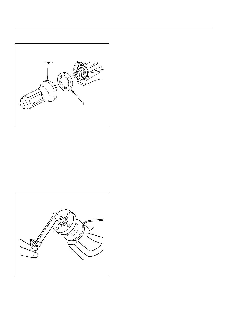
3. By using the seal installer J–37263, install a new oil

seal (1) that has grease on seal lip.

425RS004

4. Install flange.

5. The pinion washer and a new nut while holding the

pinion flange with J–8614–01.

• Tighten the nut until the pinion end play is just

taken up. Rotate the pinion while tightening the
nut to seat the bearings. Once there is not end
play in the pinion, the preload torque should be
checked.

• Remove J–8614–01. Using an inch-pound torque

wrench, check to make sure the pinion preload is
equal to or slightly over the reading recorded
during removal.

425RW018

6. Install propeller shaft to the frange.

7. Install bolt and nut. Tighten the bolt and nut to the

specified torque.

Torque: 63 N·m (46 lb ft)

DIFFERENTIAL (REAR)

4A2–13

Differential Assembly

 Disassembled View 

420RW018

EndOFCallout

 Legend  

 (1)  ABS Speed Sensor 
 (2)  Housing 
 (3)  Outer Pinion Bearing (Cup and Cone) 
 (4)  Outer Oil Slinger 
 (5)  Oil Seal 
 (6)  Companion Flange Assembly 
 (7)  Pinion Nut Washer 
 (8)  Pinion Nut 
 (9)  Collapsible Spacer 

 (10)  Baffle Plate 

 (11)  Inner Pinion Bearing (Cup and Cone) 

 (12)  Inner Oil Slinger 
 (13)  Pinion gear adj. Shim-Selective (Position) 
 (14)  Ring gear and Pinion Gear Assembly 
 (15)  Exciter Ring 
 (16)  Differential Case 

 (17)  Lock Pin 
 (18)  Axle Vent 
 (19)  Gasket 
 (20)  Cover and Clip Assembly 
 (21)  Fill Plug (with Magnet) 
 (22)  Mounting Bracket
 (23)  Side Bearing Cap Bolt 
 (24)  Side Bearing Cap 
 (25)  Drive Gear Bolts 
 (26)  Differential Adjustment Shims (Side Bearing 

Preload and Ring Gear/Pinion Backlash) 

 (27)  Side Bearing (Cup and Cone) 
 (28)  Differential Shaft 
 (29)  Differential Side Gears 
 (30)  Side Gear Thrust Washer
 (31)  Pinion Mate Gears 
 (32)  Thrustwasher-Differential Pinion Mate Gear 

4A2–14

DIFFERENTIAL (REAR)

Inspecting the Axle Before
Disassembly

1. Remove the axle cover from the rear axle and drain

the axle lubricant into a suitable container.

2. Check ring gear backlash. Refer to BACKLASH

ADJUSTMENT in this section. This information can
be used to determine the cause of the axle problem.
It will also help when setting up the shim packs for
locating and preloading the differential cage.

3. Check case for metal chips and shavings.

Determine where these chips and shavings come
from, such as a broken gear or bearing cage.

• If possible, determine the cause of the axle

problem before disassembly.

Disassembly

1. Remove axle shafts.

• Refer to axle shaft replacement in this section.

2. Remove ABS sensor.

3. Remove bearing caps and bolts.

• Mark the caps and the housing as left and right.

CAUTION:  Bearing caps are machined with the
housing and must be assembled in the same
position as removed.   Note the matched letter
stamped on the caps and carrier.   When assembled,
the letters on the caps must agree in both the
hosizontal and vertical position with the letters on
the carrier.

420RW003

4. Remove Differential case.

• Pry the case from the axle housing at the

differential“window”.

420RW010

5. Remove side bearing outer races and shims.

• Mark the races and shims as left and right, and

place them with the bearing cups.

6. Remove differential side bearings using remover J–

42379 and plug J–39830.

• Select insert ; 303174 and collet halves ; 44801 in

remover kit J–42379.

415RW003

7. Remove ring gear bolts.

• Ring gear bolts use right handed threads.

CAUTION:  DO not pry the ring gear from the case.
This will damage the ring and the differential case.

DIFFERENTIAL (REAR)

4A2–15

8. Remove ring gear from the differential.

• Drive the ring gear off with a brass drift if

necessary.

• Check drive pinion bearing preload.

425RW018

• Check the pinion assembly for looseness by

moving it back and forth. (Looseness indicates
excessive bearing wear.)

9. Remove pinion flange nut and washer.

•  Use flange holder J–8614–01 to hold the pinion

flange.

10. Remove pinion flange.

• Use flange holder J–8614–01 to remove the

pinion flange.

415RS018

11. Remove pinion from the axle housing.

• Thread the pinion nut halfway onto the pinion.

• Drive the pinion out of the housing with a hammer

and a soft drift.

• Remove the nut and then remove the pinion.

12. Remove collapsible spacer(1).

415RW011

13. Remove outer seal, outer oil slinger and outer pinion

bearing.

14. Remove inner bearing, inner oil slinger and shim

from the pinion.

• Press the bearing off the pinion using remover J–

42379.

415RW004

• Select insert ; 303174 and collet halves ; 44801 in

remover kit J–42379.

• Remove the shim.

15. Remove bearing cups and baffle plate from the axle

housing using a hammer and a punch.

• Work the cups out of the housing evenly, moving

the punch back and forth between one side of the
cup and the other.

• The baffle plate will be destroyed and should be

replaced with a new one.


Content   ..  1134  1135  1136  1137   ..