Content .. 1104 1105 1106 1107 ..
Isuzu Amigo / Axiom / Trooper / Rodeo / VehiCross. Manual - part 1106
FRONT SUSPENSION
3C–11
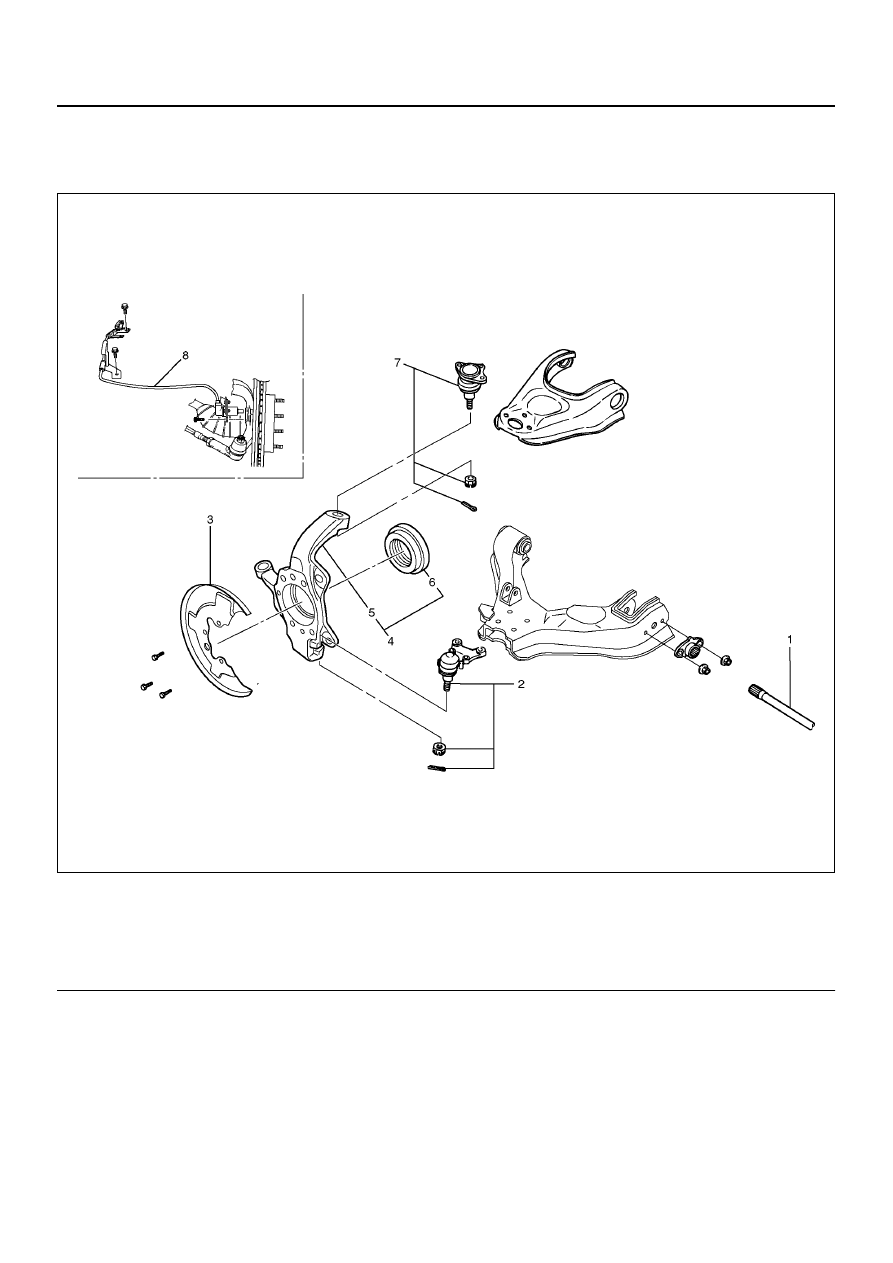
Knuckle
Knuckle and Associated Parts
410R200002
EndOFCallout
Removal
1. Raise the vehicle and support the frame with
suitable safety stands.
2. Remove wheel and tire assembly. Refer to Wheel in
this section.
3. Remove the brake caliper. Refer to Disc Brakes in
Brake section.
4. Remove the disk rotor. Refer to Disk Brakes in
Brake section.
5. Remove the hub assembly. Refer to Front Hub and
Disk in this section.
6. Remove tie–rod end from the knuckle. Refer to
Power Steering Unit in Steering section.
7. Remove the speed sensor from the knuckle.
8. Loosen torsion bar by height control arm adjust bolt,
then remove torsion bar. Refer to Torsion Bar in this
section.
9. Remove wheel speed sensor. (4x4 model)
Legend
(1) Torsion Bar
(2) Lower Ball Joint, Nut and Cotter Pin
(3) Back Plate
(4) Knuckle Assembly
(5) Knuckle
(6) Oil Seal
(7) Upper Ball Joint, Nut and Cotter Pin
(8) Wheel Speed Sensor (4x4 model)