Content .. 1103 1104 1105 1106 ..
Isuzu Amigo / Axiom / Trooper / Rodeo / VehiCross. Manual - part 1105
FRONT SUSPENSION
3C–7
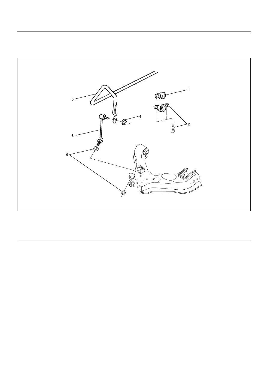
Stabilizer Bar
Stabilizer Bar and Associated Parts
410R100001
EndOFCallout
Removal
1. Raise the vehicle and support the frame with
suitable safety stands.
2. Remove the stone guard.
3. Remove wheel and tire assembly. Refer to Wheel
Replacement in this section.
4. Remove nut (4) and (6).
CAUTION: Be careful not to break the ball joint
boot.
5. Remove link.
6. Remove bracket.
7. Remove stabilizer bar.
8. Remove rubber bushing.
Inspection and Repair
Make necessary correction or parts replacement if wear,
damage, corrosion or any other abnormal condition are
found through inspection.
Check the following parts :
• Stabilizer bar
• Rubber bushing
• Link ball joint
Installation
1. Install rubber bushing.
2. Install stabilizer bar.
3. Install bracket and bolt, then tighten it to the
specified torque.
Torque: 25 N·m (18 lb ft)
4. Install link.
5. Install nut (4),(6) and washer, then tighten it to the
specified torque.
Torque: 50 N·m (37 lb ft)
Legend
(1) Rubber Bushing
(2) Bracket and Bolt
(3) Link
(4) Nut
(5) Stabilizer Bar
(6) Nut and Washer