Isuzu Amigo / Axiom / Trooper / Rodeo / VehiCross. Manual - part 1074


  Index      Isuzu     Isuzu Amigo / Axiom / Trooper / Rodeo / VehiCross - service repair manual 1999-2002 year


Search            


Content   ..  1072  1073  1074  1075   ..


Isuzu Amigo / Axiom / Trooper / Rodeo / VehiCross. Manual - part 1074


1A–18 HEATING, VENTILATION AND AIR CONDITIONING (HVAC)

Installation

To install, follow the removal steps in the reverse order,
noting the following points:

1. Apply grease to the sub-lever and to the abrasive

surface of the heater unit.

2. After installing the link unit, check to see if the link unit

operates correctly.

Blower Assembly

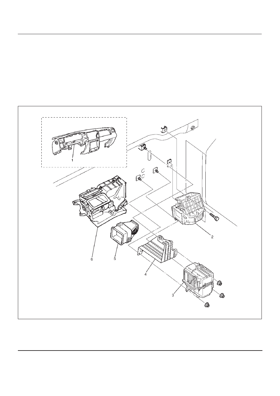
Blower Assembly and Associated Parts

873R100001

Legend

(1) Instrument Panel Assembly
(2) Blower Assembly
(2) Blower Assembly

(3) Evaporator Assembly (A/C only)
(4) Knee Bolster Bracket
(5) Duct
(6) Heater Unit

HEATING, VENTILATION AND AIR CONDITIONING (HVAC) 1A–19

Removal

1. Disconnect the battery ground cable.
2. Discharge and recover refrigerant (with air

conditioning).

D

Refer to Refrigerant Recovery in this section.

3. Remove instrument panel assembly.

D

Refer to Instrument Panel Assembly in Body and
Accessories section.

4. Disconnect resistor connector.

5. Remove knee bolster bracket.
6. Remove duct.
7. Remove evaporator assembly (A/C only).

D

Refer to Evaporator Assembly in this section.

8. Disconnect blower motor connector.
9. Remove blower assembly.

Installation

To install, follow the removal steps in the reverse order.

Blower Link Unit and / or Mode door

Disassembled View

873RY00007

Legend

(1) Blower Assembly
(2) Upper Case
(3) Mode Door

(4) Lower Case
(5) Intake Actuator
(6) Sub Lever
(7) Door Lever

Removal

1. Disconnect the battery ground cable.
2. Discharge and recover refrigerant (with air

conditioning).

D

Refer to Refrigerant Recovery in this section.

3. Remove blower assembly.

D

Refer to Blower Assembly in this section.

4. Remove intake actuator.

5. Remove lower case.

1A–20 HEATING, VENTILATION AND AIR CONDITIONING (HVAC)

6. Separate the upper case and slit the lining parting

face with a knife.

873RS002

7. Pull out the mode door while raising up the catch of

door lever.

8. Remove sub-lever.
9. Remove door lever.

Installation

To install, follow the removal steps in the reverse order,
noting the following points:

1. Apply grease to the door lever and to the abrasive

surface of the upper case.

2. Apply an adhesive to the parting face of the lining

when assembling the upper case.

HEATING, VENTILATION AND AIR CONDITIONING (HVAC) 1A–21

Blower Motor

Blower Motor and Associated Parts

873RS004

Legend

(1) Blower Motor Connector
(2) Blower Motor Assembly
(3) Clip

(4) Fan
(5) Blower Motor
(6) Attaching Screw

Removal

1. Disconnect the battery ground cable.
2. Remove blower motor connector.
3. Remove attaching screw.
4. Remove blower motor assembly.
5. Remove clip.
6. Remove fan.
7. Remove blower motor.

Installation

To install, follow the removal steps in the reverse order.


Content   ..  1072  1073  1074  1075   ..