Isuzu Amigo / Axiom / Trooper / Rodeo / VehiCross. Manual - part 1061


  Index      Isuzu     Isuzu Amigo / Axiom / Trooper / Rodeo / VehiCross - service repair manual 1999-2002 year


Search            


Content   ..  1059  1060  1061  1062   ..


Isuzu Amigo / Axiom / Trooper / Rodeo / VehiCross. Manual - part 1061


10A–2 CRUISE CONTROL SYSTEM

2. RESUME/ACCEL Switch Function

1. Resume Function: When the RESUME/ACCEL

switch is turned on/off after the system is temporarily
deactivated by pressing the brake or clutch pedal
while the vehicle is running, the vehicle resumes the
speed stored before the system was released, and
the vehicle automatically runs at the stored speed .

2. Accelerate Function: When the RESUME/ACCEL

switch is kept on after the system is released
completely, the vehicle accelerates its speed during
that time.  The vehicle speed at which the vehicle was
running when the switch was turned off is stored in the
memory, and the vehicle automatically returns to this
speed.

3. Tap-up Function: When the RESUME/ACCEL

switch is turned on and off instantaneously while the
vehicle is running, the vehicle accelerates a mile for
each on/off operation.  The vehicle speed at which the
vehicle was running when the switch was turned off
last is stored in the memory, and the vehicle
automatically returns to this stored speed.

3. CANCEL Function

1. Temporary Cancellation: 

D

When the cancel switch is turned on.

D

When the brake pedal is pressed.

D

When the clutch pedal is pressed. (M/T)

D

When the select lever is shifted to any position other
than “D”, “3”, “2”. (A/T)

D

When the cancel switch is operated.

D

When the vehicle speed exceeds about 12.5mph
over the vehicle speed stored in the memory.

D

Turning the RESUME/ACCEL switch will return the
vehicle to the speed stored in the cruise control
memory.

D

When the vehicle speed gets lower than 22.5 mph
(36 km/h).

2. Complete Cancellation:

D

When the starter switch or the main switch is turned
off.

D

When the fail-safe function is activated.
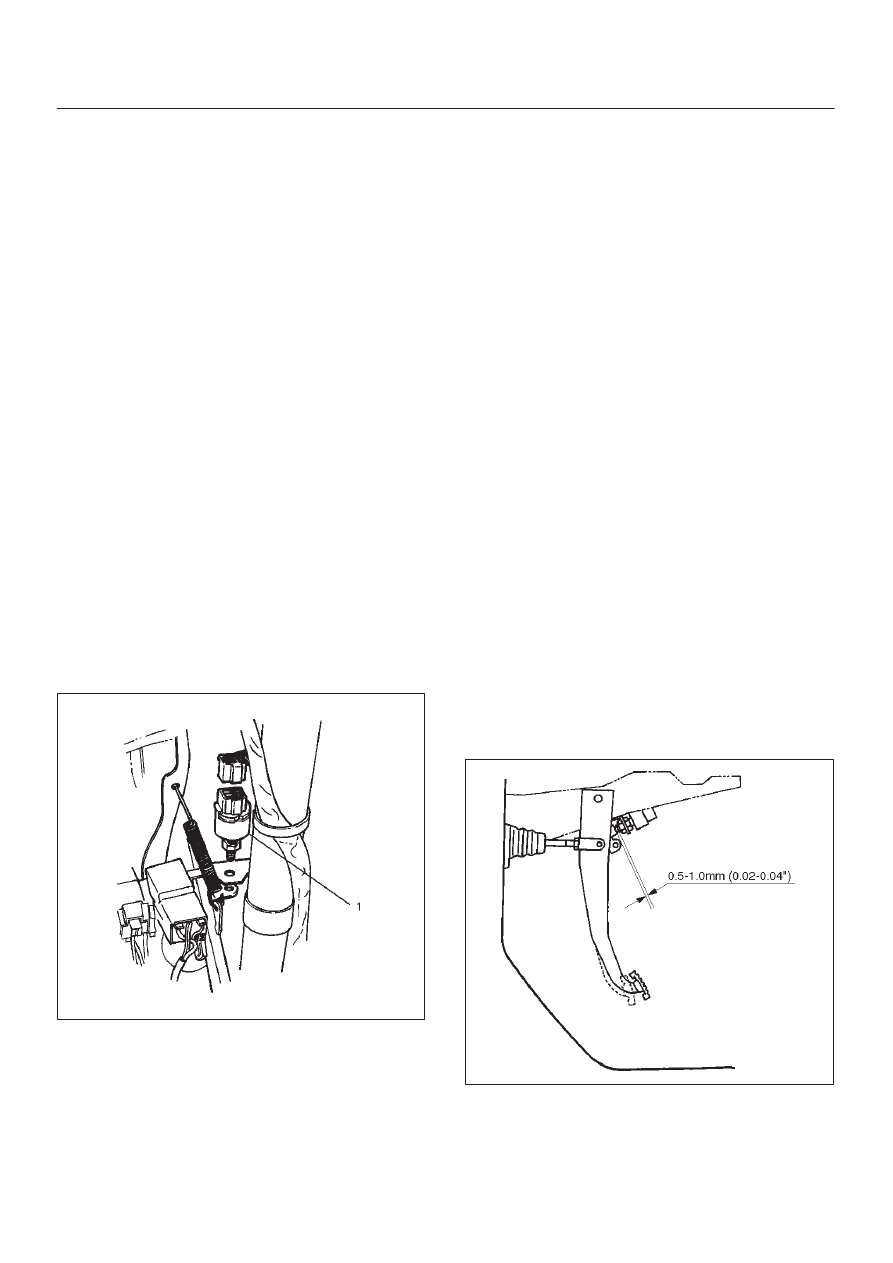
Brake Switch

Removal

1. Disconnect the battery ground cable.
2. Remove the brake switch (1).

D

Disconnect the connector.

D

Loosen the lock nuts of the switch.

D

Remove the switch by turning it.

310RS004

Installation

To install, follow the removal steps in the reverse order,
noting the following points.

1. Check to see if the brake pedal has been returned by

the return spring to the specified position.

2. Turn the switch clockwise until the tip of the threaded

portion of the brake switch contacts the pedal arm.

3. Turn the switch counterclockwise until the space

between the tip of the threaded portion and the pedal
arm is 0.5 to 1.0 mm (0.02-0.04 in.) as shown in the
figure.

310RS003

10A–3

CRUISE CONTROL SYSTEM

Adjustment

1. Check to be sure that the brake pedal (3) has been

completely returned by the return spring.

2. Disconnect the switch connector.
3. Loosen the lock nut (1) of the switch (2).
4. Turn the switch clockwise until the tip of screw portion

of the brake pedal hits the pedal arm.

5. Turn the switch counterclockwise until the clearance

between the tip of the screw portion and the pedal arm
becomes 0.5 to 1.0 mm (0.02-0.04 in).

6. Tighten the lock nut.
7. Connect the switch connector.

310RW006

Clutch Switch

Removal and Installation

Refer to the Clutch Control removal and installation steps
in Clutch section.

Adjustment

1. Check to be sure that the clutch pedal (1) has been

completely returned by the return spring.

2. Disconnect the switch connector.
3. Loosen the lock nut (2) of the switch (3).
4. Push the switch by hand until the push rod cannot be

seen from the tip portion of the switch.

5. Give the switch one reverse rotation.
6. Tighten the lock nut.
7. Connect the switch connector.

203RW002

10A–4 CRUISE CONTROL SYSTEM

Starter Switch

Removal

1. Disconnect the battery ground cable.
2. Remove the front console assembly (1).  Refer to the

Instrument Panel Assembly in Body Structure
section.

3. Remove the lower cluster assembly (2).  Refer to the

Instrument Panel Assembly in Body Structure
section. 

4. Remove the instrument panel driver lower cover

assembly (3).  Refer to the Instrument Panel
Assembly in Body Structure section. 

740R200050

5. Remove seven screws to remove the steering cowl

(6).

6. Disconnect the connector, remove the screw (4) and

then remove the starter switch (5).

431RW005

Installation

To install, follow the removal steps in the reverse order,
noting the following point.

1. When installing the steering cowl (10), be sure to pass

the harnesses through the route as shown in the
figure so that the starter switch harness (7), the
combination switch harness (8) and the inflator
module harness (9) will not catch.

825RW058

10A–5

CRUISE CONTROL SYSTEM

Cruise Control Main Switch

Removal

1. Disconnect the battery ground cable.
2. Remove the front console assembly (1).  Refer to the

Instrument Panel Assembly in Body Structure
section.

3. Remove the lower cluster assembly (2). Refer to the

Instrument Panel Assembly in Body Structure
section.

4. Remove the instrument panel driver lower cover

assembly (3).  Refer to the Instrument Panel
Assembly in Body Structure section.

740R200050

5. Remove the instrument panel cluster assembly (5).

Refer to the Instrument Panel Assembly in Body
Structure section.

6. Disconnect the and push the lock from the side of the

instrument panel cluster assembly to remove the
cruise control main switch (4).

821RW079

Installation

To install, follow the removal steps in the reverse order,
noting the following point.

1. Push in the switch with your fingers until the switch is

locked securely.

Cruise Control Switch (Combination Switch)

Removal and Installation

Refer to the Lighting Switch (Combination Switch)
removal and installation steps of Lighting System in Body
and Accessories section.

Powertrain Control Module (PCM)

Removal and Installation

Refer to Powertrain Control Module (PCM) in Engine
section.

Mode Switch

Removal and Installation

Refer to the Mode Switch removal and installation steps
in Automatic Transmission section.


Content   ..  1059  1060  1061  1062   ..