Isuzu Amigo / Axiom / Trooper / Rodeo / VehiCross. Manual - part 102
DRIVE LINE CONTROL SYSTEM (TOD)
4B2–26
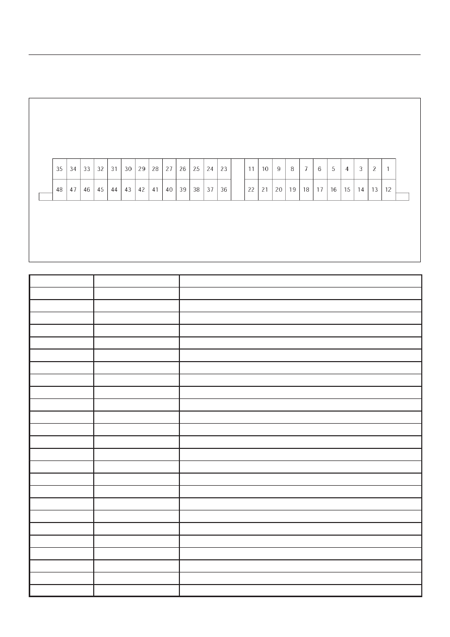
Checking Failed Pin
Connector Pin Assignment
D
TOD control unit pin assignment
D04RY00011
No.
NAME
CONTENTS
1
N.C
Not used
2
ENG REV
Engine Speed
3
N.C
Not used
4
N.C
Not used
5
N.C
Not used
6
N.C
Not used
7
IND.A
Display Front
8
IND. C
Display Rear
9
N.C
Not used
10
N.C
Not used
11
EMC
Clutch Solenoid
12
REF
Speed Reference
13
COM (–)
Speed GND
14
VIG
Ignition
15
TPS
TPS (PWM)
16
TECH 2
TECH–2
17
N. C
Not used
18
N. C
Not used
19
IND. B
Display Auto
20
CHK TOD
Check TOD
21
N.C
Not used
22
PWR GND
Power Ground
23
ADC (+)
Axle Disconnect Output
24
COM GND
Shift Motor Position GND
25
MTR POS3
Shift Motot Position 3