Isuzu Amigo / Axiom / Trooper / Rodeo / VehiCross. Manual - part 96
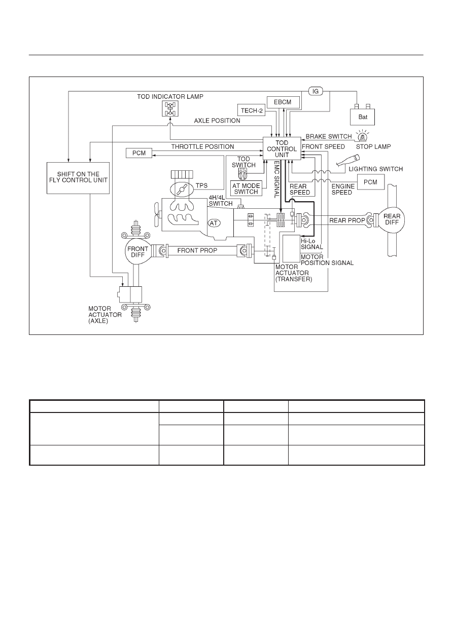
DRIVE LINE CONTROL SYSTEM (TOD)
4B2–2
General Description
412R200008
TOD (Torque on Demand) system is traction state control
system to vehicle.
Transfer Position and Drive Mode
Three drive modes can be selected through operation of
TOD switch and transfer lever.
Transfer Position
TOD SWITCH
Mode
Drive mode
HIGH
2H
RWD
Rear wheel drive
TOD
4WD
(HIGH)
Electronically controlled torque split
four wheel drive
LOW
4L
4WD
(LOW)
Low-speed mechanical lock-up four
wheel drive
The electronic control unit (ECU) judges the signals from
the TOD switch and controls the transfer drive mode and
shift-on-the-fly system status.