Isuzu Amigo / Axiom / Trooper / Rodeo / VehiCross. Manual - part 80


  Index      Isuzu     Isuzu Amigo / Axiom / Trooper / Rodeo / VehiCross - service repair manual 1999-2002 year


Search            


Content   ..  78  79  80  81   ..


Isuzu Amigo / Axiom / Trooper / Rodeo / VehiCross. Manual - part 80


DIFFERENTIAL (FRONT)

4A1–4

3. Remove the front propeller shaft. Refer to 

Front

Propeller Shaft in this section.

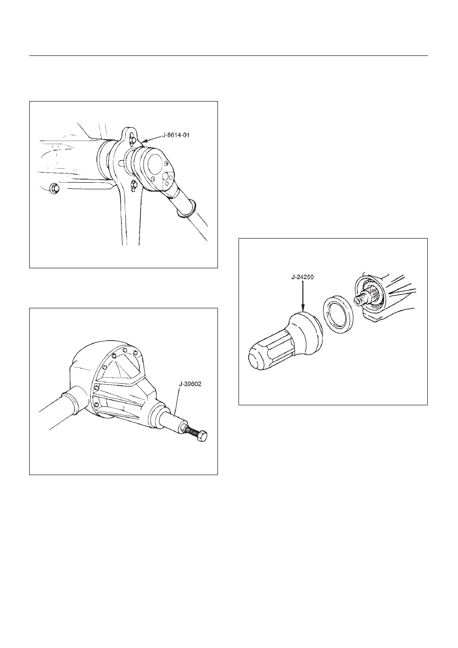
4. Remove flange nut by using pinion flange holder

J–8614–01.

415RS018

5. Remove flange.
6. Remove oil seal.
7. Remove outer bearing by using remover J–39602. 

415RS001

8. Remove collapsible spacer.

Inspection and Repair

Make necessary correction or parts replacement if wear,
damage, corrosion or any other abnormal condition are
found through inspection.
Check the following parts.

1. Seal surface of the pinion.
2. Cage bore for burns.

Installation

1. Install collapsible spacer. Discard the used

collapsible spacer and install a new one.

2. Install outer bearing.

NOTE: Do not drive in, but just temporarily set in the outer
bearing by hand, which should be indirectly pressed in
finally by tightening the flange nut.

3. Install oil seal, use oil seal installer J–24250 to install a

new oil seal that has been soaked in axle lubricant.

415RS002

4. Install flange.
5. Install flange nut, refer to 

Differential Assembly

Overhaul for flange nut reassembly in this section.

NOTE: Discard the used nut and install a new one.

4A1–5

DIFFERENTIAL (FRONT)

Front Drive Axle Assembly

Front Drive Axle Assembly and Associated Parts

412R200003

Legend

(1) Propeller Shaft
(2) Mounting Nut
(3) Front Axle Case Assembly and Front Drive

Shaft Assembly

(4) Washer

(5) Mounting Bolt
(6) Tie–rod End; Power Steering Unit
(7) Knuckle and Back Plate
(8) Hub and Disc Assembly
(9) Suspension Crossmember

DIFFERENTIAL (FRONT)

4A1–6

Removal

1. Jack up the vehicle and support it using jack stand.
2. Remove the tire and wheel.
3. Remove the stone guard.
4. Remove the brake caliper fixing bolt and hang the

caliper.  Refer to 

Disc Brakes in Brake section.

5.  Remove the antilock brake system speed sensor.

 Refer to 

Front Wheel Speed Sensor in Brake section.

6.  Remove the hub and disc assembly.

 Refer to 

Front Hub and Disc in this section.

7. Remove the propeller shaft, refer to 

Front Propeller

Shaft in this section.

8. Loosen the height control arm of the torsion bar, then

remove the torsion bar from lower control arm.
Refer to 

Torsion Bar in Suspension section.

9. Remove the suspension crossmember.

10. Remove the lower nut (1) of the stabilizer link.

11. Remove the lower bolt and nut (2) of the shock

absorber.

412RW057

12. Remove the tie-rod end from the knuckle.  Refer to

Power Steering Unit in Steering Section.

13. Disconnect the hose of the shift on the fly.
14. Disconnect the actuator connector.
15. Remove the bolts and nuts of the lower control arm

(Frame side), then disconnect the lower control arm
from frame.

16. Disconnect between the right side upper control arm

and the knuckle, then remove the knuckle with lower
control arm.

CAUTION: When removing the knuckle, be careful
not to damage the oil seal inside of the knuckle.

410RW008

17. Support the differential case by the jack.
18. Remove the front axle mounting bolts and nuts, lower

the jack slowly.  Remove the left side drive shaft end
from the knuckle, then lower the axle assembly from
the vehicle.

CAUTION:
1. Make sure the axle assembly is supported

securely when performing repairs. 

2. Do not damage the power steering unit when

performing the repairs. 

3. Do not damage the shift–on–the fly hose bracket

when performing the repairs. 

Installation

1. Support the differential case with a jack.
2. Jack up the front drive axle assembly, install the left

side drive shaft to the knuckle, then install the mount
bolts and nuts.

CAUTION:
1. Do not damage the power steering unit when

performing the repairs. 

2. Do not damage the shift–on–the fly hose bracket

when performing the repairs. 

3. When installing the drive shaft to the knuckle, be

careful not to damage the oil seal inside of the
knuckle.

4A1–7

DIFFERENTIAL (FRONT)

3. Tighten the mounting bolts and nuts to the specified

torque.

Torque: 168 N·m (124 lb ft)

412R200004

4. Install the right side knuckle with lower control arm to

the upper control arm.
Refer to 

Knuckle in Suspension section.

CAUTION: Carefully insert the drive shaft into the
knuckle, to avoid damaging the oil seal. 

5. Align the bolt hole of the lower control arm, then install

the bolts and nuts.

NOTE: Adjust the buffer clearance before tightening the
bolts and nuts of the lower control arm.

6. Install the hose of the shift on the fly.
7. Install the actuator connector of the shift on the fly.
8. Install the tie-rod end of the power steering unit to the

knuckle, tighten the nut to the specified torque.

Torque: 118 N·m (87 lb ft)

9. Install lower bolts and nuts of the shock absorber,

tighten it to the specified torque.

Torque: 93 N·m (69 lb ft)

10. Install lower nuts of the stabilizer link, tighten it to the

specified torque.

11. Install the suspension crossmember.

12. Install the torsion bar.

Refer to 

Torsion Bar in Suspension section.

13. Install the front propeller shaft.

Refer to 

Front Propeller Shaft in this section.

14. Install the hub and disc assembly and adjust the

bearing preload.
Refer to 

Front Hub and Disc in this section.

15. Install the wheel speed sensor of the antilock brake

system.

16. Install the brake caliper.  Tighten the bolt of the caliper

bracket to the specified torque.

Torque: 50 N·m (37 lb ft)

17. Install the stone guard.

18. Install the tire and wheel.
19. Lower the vehicle, adjust the trim height.

Refer to 

Trim Height Adjustment in Steering section.

20. Tighten the bolts and nuts of the lower control arm to

the specified torque.
Refer to 

Lower Control Arm in Suspension section.


Content   ..  78  79  80  81   ..