Isuzu Amigo / Axiom / Trooper / Rodeo / VehiCross. Manual - part 26


  Index      Isuzu     Isuzu Amigo / Axiom / Trooper / Rodeo / VehiCross - service repair manual 1999-2002 year


Search            


Content   ..  24  25  26  27   ..


Isuzu Amigo / Axiom / Trooper / Rodeo / VehiCross. Manual - part 26


HEATING, VENTILATION AND AIR CONDITIONING (HVAC) 1A–75
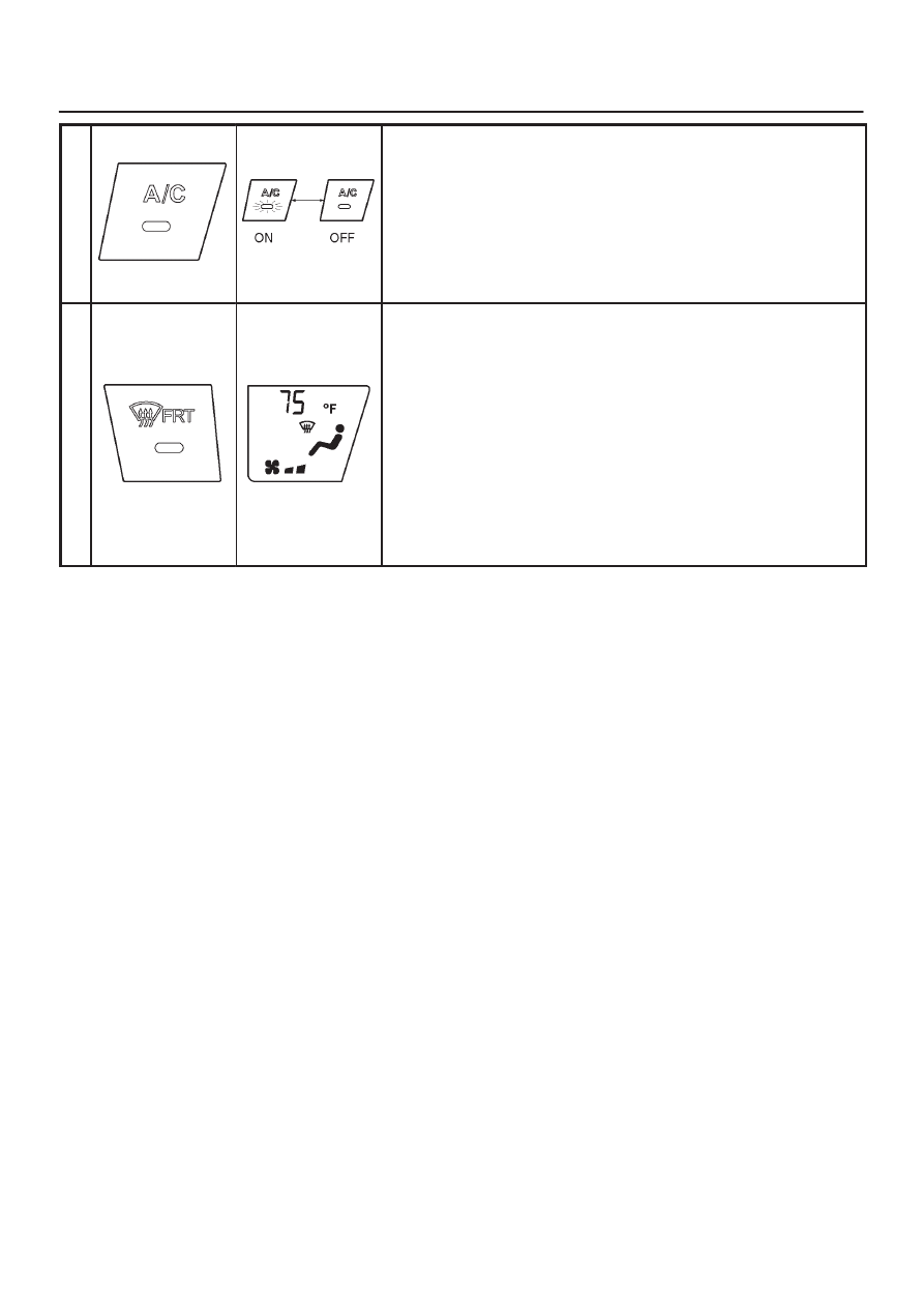
A

/

C

·

S

w

i

t

c

h

When the A/C switch is pressed, the LED light goes out and the
compressor turns off. If the switch is pressed again, the LED light
turns on and the compressor begins to operate.

The air conditioner will not operate if the fan switch is off.
During manual DEF or D/F operation, the A/C LED will turn on or off
in response to switch operation. However, the compressor remains
on regardless of switch position.

D

E

F


M

o
d
e


S

w

i

t

c

h

When the defrost switch (DEF) is pressed, air flows from the de-
froster outlets. The compressor is on and blower speed is automati-
cally controlled. Air intake is from outside the vehicle (FRESH). The
defroster symbol appears on the display.

When the defrost switch (DEF) is pressed again, the unit returns to
the settings in use before the defroster was turned on.

1A–76 HEATING, VENTILATION AND AIR CONDITIONING (HVAC)

I

Pressing the intake switch permits manual control of air intake and/
or recirculation.

I

n

t

a

k

e


S

w

i

t

c

h

If the intake switch is pressed during manual DEF or D/F, the intake
switch LED briefly turns on. However, outside air intake (FRESH)
continues.

T

e

m

p
e

r

a

t

u

r

e


C

o
n

t

r

o

l

S

w

i

t

c

h

The display panel temperature setting can be set from 18

°

C (65

°

F)

to 32

°

C (90

°

F).

Pressing and immediately releasing the 

Y

 switch increases the

temperature setting in -17

°

C (1

°

F) increments. If the switch is

pressed and held, the temperature setting increases rapidly.
Pressing and immediately releasing the 

B

 switch decreases  the

temperature setting in -17

°

C (1

°

F) decrements. If the switch is

pressed and held, the temperature setting decreases rapidly.
When the temperature setting is at 32

°

C (90

°

F), the unit is set to

maximum heat mode.
When the temperature setting is at 18

°

C (65

°

F), the unit is set to

maximum cooling mode.

HEATING, VENTILATION AND AIR CONDITIONING (HVAC) 1A–77

Overview of Construction, Movement
and Control of Major Parts of
Automatic Air Conditioner System

Automatic Air Conditioner Control Unit

Equipped with the built-in micro-computer, this control
unit operates on signals from sensors and input signals
from switches to offer total control of the blower fan, and
actuators used for the mode door, intake door and air mix
door.
Its self-diagnosis function enables quicker access to a
failed part and its more accurate troubleshooting.

In Car Sensor

It is a sensor used for detecting room temperature of a
vehicle.  This sensor converts a given room temperature
into a resistance value before entering the data to the
automatic air conditioner control unit.
This in car sensor unites the power driven aspirator and
the motor fan so that a small amount of room air may be
constantly fed to the sensor.
This sensor is provided on the right side of meter cluster.

865R200001

Legend

(1) Meter Cluster
(2) In Car Sensor

Ambient Sensor

This sensor is used for detecting temperature outside the
vehicle.  It converts a given outside air temperature into a
resistance value before entering the data to the automatic
air conditioner control unit.
Thermal effects from the condenser and radiator during
idling after a run can be measured and offset the
automatic amplifier.
This sensor is provided on the side plate situated at upper
right side of the condenser.

875R200017

Legend

(1) Ambient Sensor
(2) Condenser Assembly

Duct Sensor

The duct sensor is the sensor to detect temperature
change of the side of evaporator blower coming by fresh
recirculation of intake door or “on” “off” of compressor.
The temperature is converted to resistant rate.
And it works as thermostat to control to prevent freezing
of evaporator.
This sensor is installed in the upper case of evaporator.

874R200001

Legend

(1) Sensor Part
(2) Duct Sensor Assembly
(3) Evaporator Assembly

1A–78 HEATING, VENTILATION AND AIR CONDITIONING (HVAC)

Sun Sensor

It is a photodiode used for detecting quantity of solar
radiation.  This sensor converts the offset signal
generated by changes in the interior temperature (which
results from fluctuations in solar radiation) into
photoelectric current to enter into the automatic air
conditioner control unit.
This sensor is provided at top of the center cluster upper.

865R200002

Legend

(1) Sun Sensor
(2) Center Cluster Upper

Power Transistor

Receiving base current from the automatic air conditioner
control unit, the power transistor implements stage-less
speed change of the blower fan motor.  This transistor is
provided on the evaporator.

874R200009

Legend

(1) Evaporator Assembly
(2) Power Transistor

Max Hi Relay

This relay turned on or off by the signal from the automatic
air conditioner control unit.  As the Max Hi relay is turned
on, supply voltage is directly fed to the blower fan motor to
select the Max Hi mode.

873RY00005

Legend

(1) Blower Unit
(2) Max High Relay


Content   ..  24  25  26  27   ..