Isuzu Amigo / Axiom / Trooper / Rodeo / VehiCross. Manual - part 21


  Index      Isuzu     Isuzu Amigo / Axiom / Trooper / Rodeo / VehiCross - service repair manual 1999-2002 year


Search            


Content   ..  19  20  21  22   ..


Isuzu Amigo / Axiom / Trooper / Rodeo / VehiCross. Manual - part 21


HEATING, VENTILATION AND AIR CONDITIONING (HVAC) 1A–55

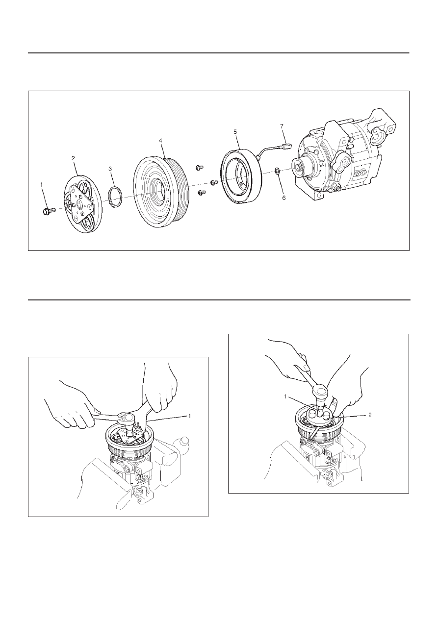
Magnetic Clutch Assembly (DKV-14G Type)

Parts Location View

871RX025

Legend

(1) Drive Plate bolt
(2) Drive Plate
(3) Snap Ring

(4) Pulley Assembly
(5) Field Coil
(6) Shim (s)
(7) Lead Wire

Removal

1. Using drive plate holder J-33939 (1) to prevent the

drive plate from rotating, then remove the drive plate
bolt.

871RX029

2. Remove drive plate by using drive plate puller

J-33944-A (2) and forcing screw J-33944-4 (1).

871RX023

3. Remove shim (s).

1A–56 HEATING, VENTILATION AND AIR CONDITIONING (HVAC)

4. Remove snap ring (1) by using snap ring pliers.

871RY00029

5. Remove pulley assembly by using pulley puller pilot

J-38424 (2), pulley puller J-8433 (1) and pulley puller
leg J-24092-2 (3).

871RY00033

6. Loosen screw and disconnect the field coil wire

connector.

871RY00030

7. Loosen three screws and remove the field coil.

871RY00034

HEATING, VENTILATION AND AIR CONDITIONING (HVAC) 1A–57

Inspection and Repair

Drive Plate

If the frictional surface shows signs of damage due to
excessive heat, the drive plate and pulley should be
replaced.

Pulley Assembly

Check the appearance of the pulley assembly.  If the
frictional surface of the pulley shows signs of excessive
grooving due to slippage, both the pulley and drive plate
should be replaced.  The frictional surfaces of the pulley
assembly should be cleaned with a suitable solvent
before reinstallation.

Coil

Check coil for loose connector or cracked insulation.

Installation

1. Install field coil.

D

Align the located portion (1) of the field coil and
compressor.

871RY00035

D

Tighten the mounting screw to the specified torque.

Torque: 5N·m (44 lb in)

2. Connect the lead wire connector with the rubber hold

and tighten the screw.

3. Install pulley assembly by using pulley installer

J-33940-A (2) and drive handle J-8092 (1).

871RY00032

4. Install snap ring.
5. Install shim (s).
6. Install the drive plate to the compressor drive shaft

together with the original shim(s)(1).  Press the drive
plate by hand.

871RY00031

1A–58 HEATING, VENTILATION AND AIR CONDITIONING (HVAC)

7. Install drive plate bolt by using drive plate holder

J-33939 (1) to prevent the drive plate from rotating.

871RX029

D

Tighten the drive plate bolt to the specified torque.

Torque: 13 N·m (113 lb in)

D

After tightening the drive plate bolt, check to be sure
the pulley rotates smoothly.

D

Check to be sure that the clutch clearance is
between 0.3-0.6 mm (0.01-0.02 in.)

871RY00028

Legend

(1) Dial Gauge
(2) Pulley Assembly
(3) Field Coil Wire Connector

D

If necessary, install adjusting shim(s).

D

Adjusting shims are available in the following
thickness.

Thickness

D

0.1 mm (0.0039 in.)

D

0.3 mm (0.0118 in.)

D

0.5 mm (0.0197 in.)


Content   ..  19  20  21  22   ..