Isuzu Amigo / Axiom / Trooper / Rodeo / VehiCross. Manual - part 19


  Index      Isuzu     Isuzu Amigo / Axiom / Trooper / Rodeo / VehiCross - service repair manual 1999-2002 year


Search            


Content   ..  17  18  19  20   ..


Isuzu Amigo / Axiom / Trooper / Rodeo / VehiCross. Manual - part 19


HEATING, VENTILATION AND AIR CONDITIONING (HVAC) 1A–47

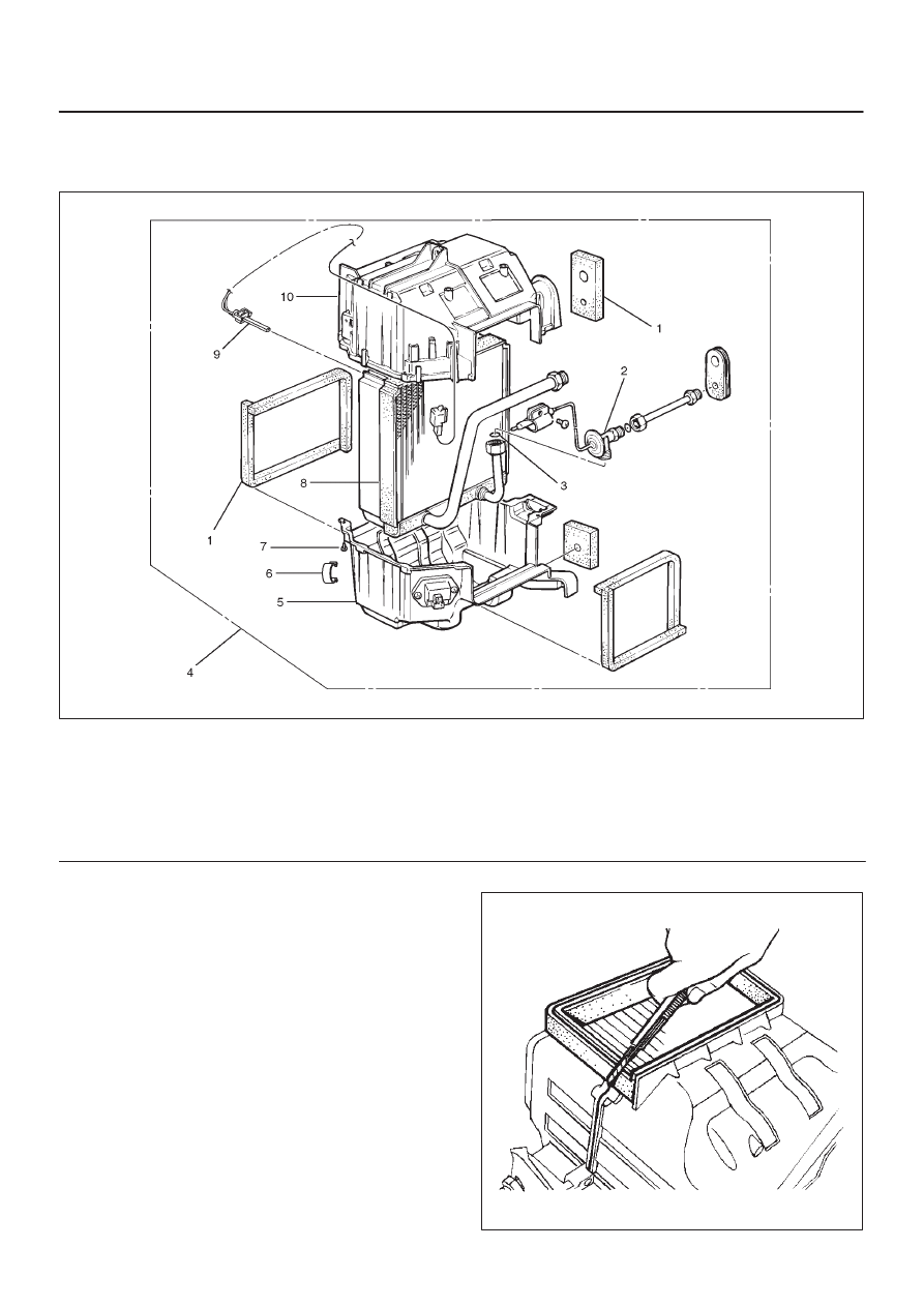
Duct Sensor, Evaporator Core and/or Expansion Valve

Disassembled View

874R200012

Legend

(1) Lining
(2) Expansion Valve
(3) O-ring
(4) Evaporator Assembly
(5) Lower Case

(6) Clip
(7) Attaching Screw
(8) Evaporator Core
(9) Duct Sensor

(10) Upper Case

Removal

1. Disconnect the battery ground cable.
2. Discharge and recover refrigerant.

D

Refer to 

Refrigerant Recovery in this section.

3. Remove evaporator assembly.

D

Refer to 

Evaporator Assembly in this section.

4. Remove the duct sensor fixing clip.

Pull the sensor from the evaporator assembly.

5. Remove clip.
6. Remove attaching screw.
7. Remove upper case.
8. Remove lower case.

D

Slit the case parting face with a knife since the lining
is separated when removing the evaporator.

874RS006

1A–48 HEATING, VENTILATION AND AIR CONDITIONING (HVAC)

D

Lift to remove the upper case.

874R200007

9. Remove evaporator core.

874R200008

10. Remove expansion valve.

D

Tear off the insulator carefully.

D

Remove the sensor fixing clip.

D

Use a back-up wrench when disconnecting all
refrigerant pipes.

Installation

To install, follow the removal steps in the reverse order,
noting the following points:

1. The sensor is installed on the core with the clip.
2. The sensor must not interfere with the evaporator

core.

3. When installing the new evaporator core, install the

duct sensor (2) to the evaporator core (1) specified
position with the clip in the illustration.

874RY00016

4. O-rings cannot be reused. Always replace with new

ones.

5. Be sure to apply new compressor oil to the O-rings

when connecting lines.

6. Be sure to install the sensor and the insulator on the

place where they were before.

7. To install a new evaporator core, add 50cc (1.7 fl. oz.)

of new compressor oil to the new core.

8. Tighten the refrigerant lines to the specified torque.

Refer to 

Main Data and Specifications for Torque

Specifications in this section.

9. Apply an adhesive to the parting face of the lining

when assembling the evaporator assembly.

HEATING, VENTILATION AND AIR CONDITIONING (HVAC) 1A–49

Refrigerant Line

Refrigerant Line and Associated Parts

852R200007

Legend

(1) Clip and Clamp
(2) Liquid Line (High-Pressure Pipe)
(3) Discharge Line (High-Pressure Hose)
(4) Condenser Air Guide

(5) Front Bumper Assembly
(6) Front Side Turn Signal Light (LH)
(7) Head Light (LH)
(8) Suction Line (Low-Pressure Pipe)

Removal

1. Disconnect the battery ground cable.
2. Discharge and recover refrigerant.

D

Refer to 

Refrigerant Recovery in this section.

3. Remove the front bumper assembly.

D

Refer to the 

Front Bumper in Body Structure

section.

4. Remove the condenser air guide.

5. Remove the front side turn signal light (LH).
6. Remove the head light (LH).
7. Remove clip and clamp.
8. Disconnect liquid line (High-pressure pipe).
9. Disconnect suction line (Low-pressure pipe) using a

back-up wrench.

10. Disconnect suction line (Low-pressure hose) using a

back-up wrench.

1A–50 HEATING, VENTILATION AND AIR CONDITIONING (HVAC)

11. Disconnect discharge line (High-pressure hose)

using a back-up wrench.

D

Use a backup wrench when disconnecting and
reconnecting the refrigerant lines.

D

When removing the refrigerant line connecting part,
the connecting part should immediately be plugged
or capped to prevent foreign matter from being
mixed into the line.

Installation

To install, follow the removal steps in the reverse order,
noting the following point:

1. O-rings cannot be reused. Always replace with new

ones. 

2. Be sure to apply new compressor oil to the O-rings

when connecting lines.

3. Tighten the refrigerant line to the specified torque.

Refer to 

Main Data and Specifications for Torque

Specifications in this section.


Content   ..  17  18  19  20   ..