Isuzu engine 4j series. Manual - part 58


  Index      Isuzu     Isuzu engine 4j series - service manual


Search            


Content   ..  56  57  58  59   ..


Isuzu engine 4j series. Manual - part 58


6A1 – 100  4JB1/4JB1T/4JB1TC/4JG2 - ENGINE

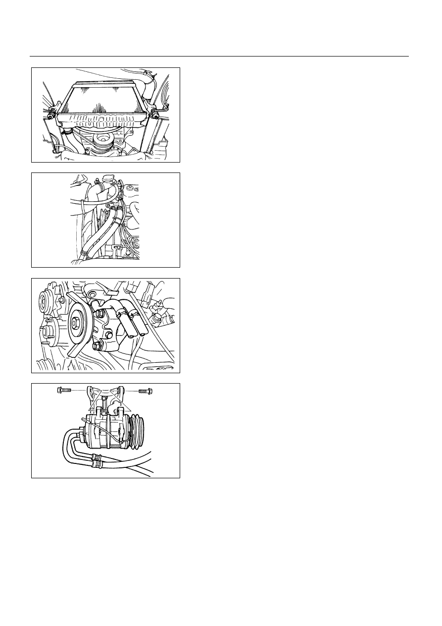
2. Radiator Assembly

1) Remove the radiator hose upper and lower.
2) Remove the reservoir tank hose
3) Remove the cushion rubbers on both sides.
4) Remove the radiator stay.

3. Intake Air Duct

4. Heater Hose

5. Engine Control Cable

Loosen the locking nut at the bracket and disconnect
accelerator cable from injection pump control lever.

6. Glow Plug Harness

7. Fuel Hose

Remove the fuel inlet hose and fuel return hose.

8. Oil Pressure Switch Harness

9. A/C Compressor Assembly

Loosen the idler pulley lock nut.

Loosen the adjust bolt then remove the drive belt.

Disconnect magnetic clutch harness connector.

Remove the A/C compressor fixing bolts and
temporally tighten the A/C compressor to chassis
frame side use the wire.

6A1-100-1.tif

6A1-100-2.tif

6A1-100-3.tif

6A1-100-4.tif

4JB1/4JB1T/4JB1TC/4JG2 – ENGINE  6A1 – 101

10. Power Steering Pump & Bracket Assembly (Power

Steering Model)
1) Loosen the idler pulley lock nut.
2) Loosen the adjust bolt then remove the drive belt.
3) Remove the pipe bracket fixing bolt and clip.
4) Remove the power steering pump fixing bolts pump to

chassis frame side use the wire.

11. Actuator Vacuum Hose (Exh. Brake Model)

Disconnect the vacuum hose from actuator side.

12. Vacuum Pump Hose (Exh. Brake Model)

Disconnect the vacuum hose from vacuum tank side
and magnetic valve side.

13. Front Exhaust Pipe

Remove the exhaust pipe fixing bolts from exhaust
manifold.

Remove the exhaust pipe stay bolt.

Remover the fixing nuts from front pipe.

14. Support Rubber

1) Right Hand

Remove two fixing nuts at the crossmember side.

6A1-101-1.tif

6A1-101-2.tif

6A1-101-3.tif

6A1-101-4.tif

6A1-101-5.tif

6A1 – 102  4JB1/4JB1T/4JB1TC/4JG2 - ENGINE

2) Left Hand

Remove two fixing nuts at the crossmember side.

15. Engine Assembly

1)  Lift engine carefully by using hoist.
2) Lift front part of engine higher than rear part of it.
3) Take out engine assembly taking care not to damage

full pipes, brake pipes and etc.

6A1-102-1.tif

4JB1/4JB1T/4JB1TC/4JG2 – ENGINE  6A1 – 103

INSTALLATION

15. Engine Assembly

Position engine mountings by using hoist.

14. Support Rubber

After all fixing bolts (left:two bolts, right:two bolts) were
inserted to every holes, and engine asm and tighten
fixing bolts to the specified torque.

N∙m (kg∙m/lb∙ft)


40 (4.1/30)


13. Front Exhaust Pipe

Connect the exhaust pipe and tighten nut to the
specified torque.

Exhaust Pipe Nut Torque

N∙m (kg∙m/lb∙ft)


69 (7.0/51)


Install the exhaust pipe stay and tighten bolt nut to the
specified torque.

Stay Bolt Nut Torque

N∙m (kg∙m/lb∙ft)


40 (4.1/30)


12. Vacuum Pump Hose (Exh. Brake Model)

Connect the vacuum hose to vacuum tank side and
magnetic valve side.

11. Actuator Vacuum Hose (Exh. Brake Model)

Connect the vacuum hose to actuator.

6A1-103-1.tif

6A1-103-2.tif

6A1-103-3.tif

6A1-103-4.tif


Content   ..  56  57  58  59   ..