Isuzu engine 4j series. Manual - part 42


  Index      Isuzu     Isuzu engine 4j series - service manual


Search            


Content   ..  40  41  42  43   ..


Isuzu engine 4j series. Manual - part 42


6A1 – 36  4JB1/4JB1T/4JB1TC/4JG2 - ENGINE

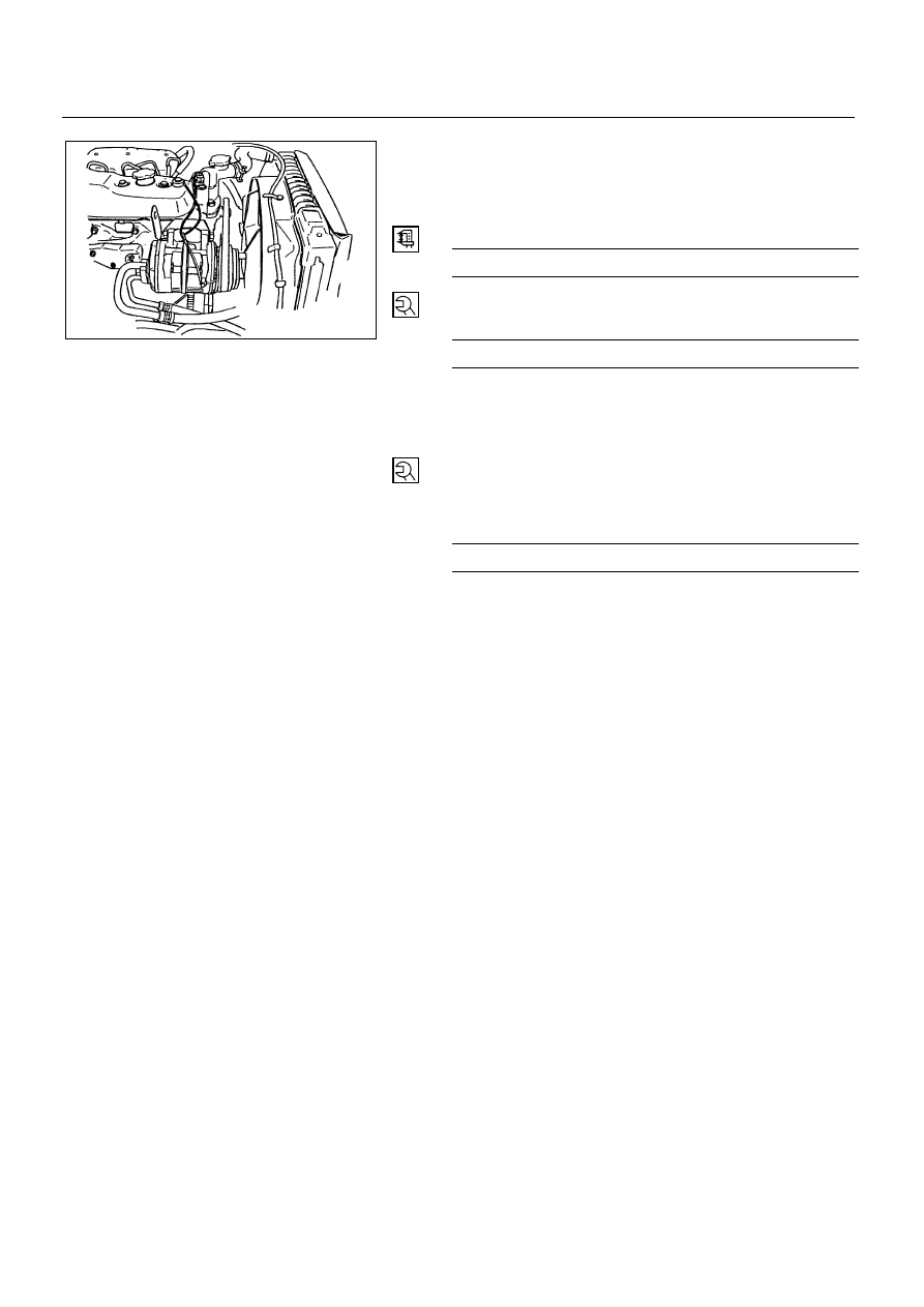
3. Power Steering Pump Drive Belt (P/S pump model)

Install PS pump drive belt and adjust belt tension.

Depress the drive belt mid-portion with a 98N
(10kg/22lb) force.

Drive Belt Deflection

mm (in)


8 (0.31) - 12 (0.47)


Tighten the idler lock nut to the specified torque.

N∙m (kg∙m/lb∙ft)


27 (2.8/20)


2. Fan Shroud

Install the fan shroud and reservoir tank hose.

1. Cooling Fan Assembly

Mount fan pulley, distance piece, and cooling fan asm
(in this order) on the water pump, and tighten to the
specified torque.

N∙m (kg∙m/lb∙in)


8 (0.8/69)


Connect battery ground cable.

Pour coolant.

Start the engine and check coolant leakage.

6A1-36-1.tif

4JB1/4JB1T/4JB1TC/4JG2 – ENGINE  6A1 – 37

CYLINDER HEAD ASSEMBLY AND GASKET

REMOVAL

Preparation:

Disconnect battery ground cable.

Drain coolant from the radiator and engine.

1. Radiator Hose Upper

Disconnect upper radiator hose from engine side.

6A1-37-1.tif

Removal steps

1.  Radiator hose upper
2. Heater hose
3.  A/C Compressor drive

belt

4. Engine harness
5.  Air intake duct
6. Injection pipe
7.  Leak off pipe
8. PCV hose
9.  Glow plug harness
10. Oil level gauge guide

tube

11. Oil cooler water pipe
12. A/C Compressor

Assembly

13. Vacuum actuator hose
14. Front exhaust pipe
15. By-pass hose
16. Cylinder head cover
17. Rocker arm shaft
18. Push rod
19. Cylinder head

Assembly

20. Cylinder head gasket

Installation steps

To install, follow the
removal steps in the
reverse order.

6A1 – 38  4JB1/4JB1T/4JB1TC/4JG2 - ENGINE

2. Heater Hose

Disconnect heater hose from heater pipe.

3. A/C Compressor Drive Belt

Loosen idler lock nut.

Loosen adjust bolt and remove drive belt.

4. Engine Harness

Disconnect harness connectors from units on
thermostat housing.

5. Air Intake Duct

Remove the clip and air intake duct.

6. Injection Pipe

Release injection pipe clip.

Remove flare nut injection pump side.

Remove flare nut injection nozzle side and remove
injection pipe.

NOTE:

Plug the injection nozzle holder and the delivery
holder to prevent the entry of foreign matters into
them.

7. Leak Off Pipe

Remove the leak off pipe side of leak off hose.

8. PCV Hose

Remove the PCV hose from air intake pipe.

6A1-38-1.tif

6A1-38-2.tif

4JB1/4JB1T/4JB1TC/4JG2 – ENGINE  6A1 – 39

9. Glow Plug Harness

10. Oil Level Gauge Guide Tube

Remove the guide tube from cylinder head.

11. Oil Cooler Water Pipe (Oil Cooler Model)

Remove the pipe fixing bolt of cylinder head rear side.

Remove the oil cooler water pipe fixing nut from inlet
manifold.

12. A/C Compressor Assembly (A/C Model)

Remove the clutch harness connector.

Remove the A/C compressor fixing bolts and
temporally tighten the A/C compressor to chassis
frame side use the wire.

13. Vacuum Actuator Hose (Exhaust Brake Model)

Remove the vacuum hoses from vacuum actuator.

14. Front Exhaust Pipe

Remove the exhaust pipe fixing bolts from exhaust
manifold.

Remove the exhaust pipe stay bolt.

6A1-39-1.tif

6A1-39-2.tif

6A1-39-3.tif

6A1-39-4.tif


Content   ..  40  41  42  43   ..