Isuzu engine 4j series. Manual - part 40


  Index      Isuzu     Isuzu engine 4j series - service manual


Search            


Content   ..  38  39  40  41   ..


Isuzu engine 4j series. Manual - part 40


6A1 – 28  4JB1/4JB1T/4JB1TC/4JG2 - ENGINE
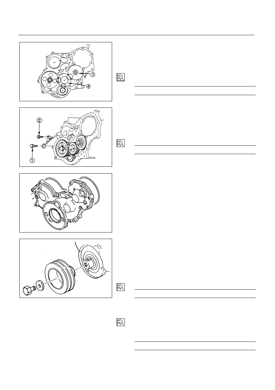
10. Idler Gear

1) Apply engine oil to the idler gear and the idler gear

shaft.

2) Align the idler gear "B" 

#

 "Z" setting mark with the

idler gear "A" 

$

 "Z-Z" setting mark.

3) Tighten the idler gear bolt to the specified torque.

N∙m (kg∙m/lb∙ft)


76 (7.7/56)


9. Oil Pipe

1) Install the oil pipe to the timing gear case and idler

gear "A".

2) Tighten the oil pipe eye bolt 

!

 and bolt 

"

 to the

specified torque.

Oil Pipe Eye Bolt Torque

N∙m (kg∙m/lb∙ft)


13 (1.3/9)


8. Timing Gear Case Cover

1) Align the gear case with the timing gear case knock

pin and then install the timing gear case cover.

2) Tighten the gear case cover bolts to the specified

torque.

7. Noise Cover Spacer

6. Noise Shield Cover

5. Crankshaft Damper Pulley

Tighten the crankshaft damper pulley bolt to the specified
torque.

NOTE:

Hold the flywheel ring gear stationary to prevent the
crankshaft from turning when tightening the damper
pulley.
Pulley Boss Bolt Torque

N∙m (kg∙m/lb∙ft)


206 (21/152)


4. Cooling Fan Assembly

Mount fan pulley, distance piece, and cooling fan
assembly (in this order) on the water pump, and
tighten to the specified torque.

N∙m (kg∙m/lb∙in)


8 (0.8/69)


6A1-28-1.tif

6A1-28-2.tif

6A1-28-3.tif

6A1-27-1.tif

4JB1/4JB1T/4JB1TC/4JG2 – ENGINE  6A1 – 29

3. AC Generator Drive Belt

Install AC Generator drive belt and adjust belt tension.

Depress the drive belt mid-portion with a 98N
(10kg/22lb) force.

Drive Belt Deflection

mm (in)


8 (0.31) - 12 (0.47)


Tighten the idler lock nut to the specified torque.

N∙m (kg∙m/lb∙ft)


27 (2.8/20)


2. Power Steering Pump Drive Belt (P/S Model)

Install Power Steering pump drive belt and adjust belt
tension.

Depress the drive belt mid-portion with a 98N
(10kg/22lb) force.

Drive Belt Deflection

mm (in)


8 (0.31)-12(0.47)


Tighten the idler lock nut to the specified torque.

N∙m (kg∙m/lb∙ft)


27 (2.8/20)


1. Fan shroud

Install the fan shroud and reservoir tank hose.

Pour coolant

Start the engine and check coolant leakage.

6A1 – 30  4JB1/4JB1T/4JB1TC/4JG2 - ENGINE

TIMING BELT (4JG2 Belt Type)

REMOVAL

Preparation:

Disconnect battery ground cable.

Drain coolant.

1. Cooling Fan Assembly

Remove clamp nut, and remove cooling fan asm,
distant pipe, and fan pulley.

2. Fan Shroud

Removal reservoir tank hose and fan shroud.

3. Power Steering Pump Drive Belt (P/S Model)

Loosen power steering pump idle pulley lock nut and
adjust bolt, and remove the drive belt.

4. A/C Compressor Drive Belt (A/C Model)

Loosen A/C compressor idle pulley lock nut and adjust
bolt, and remove the drive belt.

6A1-30-1.tif

6A1-30-2.tif

6A1-30-3.tif

4JB1/4JB1T/4JB1TC/4JG2 – ENGINE  6A1 – 31


5. AC Generator Drive Belt

Loosen AC Generator mounting bolt (under side) and
adjust plate lock bolt, and remove the drive belt.

6. Power Steering Pump Bracket Assembly (P/S Model)

Loosen power steering oil pipe bracket and clip.

Remove power steering pump bracket assembly and
hang the power steering pump bracket assembly.

7. Crankshaft Damper Pulley

8. Timing Pulley Upper Cover

9. Timing Pulley Lower Cover

10. Flange; Camshaft Pulley

6A1-31-1.tif

6A1-31-2.tif

6A1-31-3.tif

6A1-31-4.tif


Content   ..  38  39  40  41   ..