Isuzu KB P190. Manual - part 913
Battery
Page 6D1-3–12
9
Lock the doors and activate the theft deterrent system to arm the vehicle.
10
If the multimeter contains fuses, check they are serviceable.
Test Procedure
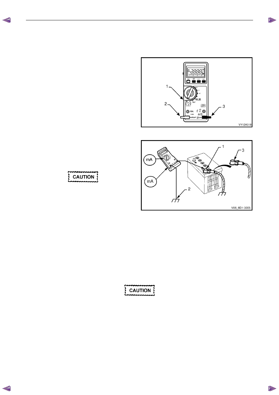
1
Switch the multimeter to the mA current range (1).
2
Connect the positive test lead (2) to the fused mA
terminal of the multimeter.
3
Connect the negative test (3) lead to the common
terminal of the multimeter.
4
Connect large alligator clips to the ends of both test
leads.
Figure 6D1-3 – 7
5
Connect the negative test lead clip to the threads of
the battery negative terminal clamp (1).
6
Connect the positive lead’s clip to the threads of a
convenient engine bolt (2).
Do not turn on the ignition switch while this
test is in progress. It will blow the
multimeter’s low current fuse.
7
Check the multimeter connections are secure.
8
Disconnect the vehicle’s main electrical earth by
removing the battery negative terminal cable retaining
nut (3) and separating the cable from the battery
clamp.
Figure 6D1-3 – 8
9
Read the vehicle’s battery saver current on the multimeter. The multimeter reading should be within 16 – 30 mA
(fluctuating).
10
If the multimeter reading is higher than specified, refer to Fault Diagnosis in this Section, otherwise restore the
vehicle to its prior condition, refer to Restore in this Section.
Fault Diagnosis
Do not open any doors during this inspection.
If the doors must be opened, reinstall the
battery terminal to the battery clamp to
protect the multimeter's fuse from blowing.
Alternatively, use the higher (10 A) fuse rated
terminal on the multimeter until the source of
the higher current draw has been found.
1
Visually inspect the vehicle for illuminated lamps and components activated by energised relays.
2
If the cause of the excessive current draw is not apparent, remove one fuse (or circuit breaker) at a time to
determine the circuit group that is drawing excess current. Refer to 8A Electrical Body & Chassis for fuse grouping
location.