Isuzu KB P190. Manual - part 728


  Index      Isuzu     Isuzu KB P190 - service repair manual 2007 year


Search            


Content   ..  726  727  728  729   ..


Isuzu KB P190. Manual - part 728


Engine Mechanical – V6 

Page 6A1–135 


Page 6A1–135 

17 

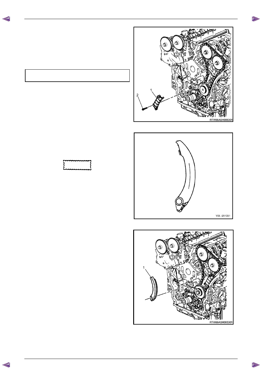
Install the left-hand secondary timing chain guide (1). 

18 

Install the secondary timing chain guide bolts (2) and 
tighten to the correct torque specification. 


Secondary timing chain guide 
attaching bolt torque specification...........20.0 – 26.0 Nm 


Figure 6A1 – 158 

19 

Ensure the left-hand secondary timing chain shoe is 
selected and orientated correctly. 


CAUTION


The left-hand secondary timing chain shoe 
is marked with the letters LH on the back 
face of the timing chain shoe. Ensure the 
correct shoe is used when installing to the 
left-hand side. 


Figure 6A1 – 159 

20 

Install the left-hand secondary timing chain shoe (1). 


Figure 6A1 – 160 

Engine Mechanical – V6 

Page 6A1–136 


Page 6A1–136 

21 

Install the left-hand secondary timing chain shoe 
bolt (1) and tighten to the correct torque specification.


N O T E  

Ensure secondary timing chain shoe is clear of 
the left-hand secondary timing chain tensioner 
mounting pad, before tightening the attaching 
bolt. 


Secondary timing chain shoe attaching 
bolt torque specification ..........................20.0 – 26.0 Nm 


Figure 6A1 – 161 

22 

Ensure the left-hand secondary timing chain tensioner 
is selected and orientated correctly. 


Figure 6A1 – 162 

23 

Reset the left-hand secondary timing chain tensioner.


N O T E  

To reset the tensioner, use a suitably sized flat 
blade screwdriver (1) or Tool No. J 45027 (4) to 
wind the plunger in a clockwise direction, into 
the tensioner shaft (2). 


Figure 6A1 – 163 

Engine Mechanical – V6 

Page 6A1–137 


Page 6A1–137 

24 

Install the tensioner shaft (1) into the left-hand 
secondary timing chain tensioner body (2). 


Figure 6A1 – 164 

25 

Compress the tensioner shaft into the body and lock 
the left-hand secondary timing chain tensioner by 
inserting Tool No. EN 46112 into the access hole in 
the side of the tensioner body. 

26 

Slowly release pressure on the left-hand secondary 
timing chain tensioner. The tensioner should remain 
compressed. 


CAUTION


If Tool No. EN 46112 (1) is not removed from  
the tensioner body (2), the tensioner 
shaft (3) will remain in the locked position 
and no tension will be placed on the timing 
chain, this will cause damage to the engine. 


Figure 6A1 – 165 

27 

Install a new left-hand secondary timing chain 
tensioner gasket (1) to the tensioner (2). 

28 

Install the left-hand secondary timing chain tensioner 
bolts through tensioner and gasket. 

29 

Ensure the left-hand secondary timing chain tensioner 
mounting surface on the left-hand cylinder head does 
not have any burrs or defects that would affect the 
sealing of the new gasket. 


Figure 6A1 – 166 

Engine Mechanical – V6 

Page 6A1–138 


Page 6A1–138 

30 

Place the left-hand secondary timing chain tensioner 
(2) into position and loosely install the bolts (1) to the 
cylinder head. 


Figure 6A1 – 167 

31 

Verify the proper placement of the left-hand 
secondary timing chain tensioner gasket tab (1). 

32 

Tighten the left-hand secondary timing chain 
tensioner bolts (2) to the correct torque specification. 


Secondary timing chain tensioner 
attaching bolt torque specification...........20.0 – 26.0 Nm 


Figure 6A1 – 168 

33 

Release the left-hand secondary timing chain 
tensioner (1) by pulling out Tools No. EN 46112 (2) 
and unlocking the tensioner shaft. 


Figure 6A1 – 169 


Content   ..  726  727  728  729   ..