Isuzu KB P190. Manual - part 712


  Index      Isuzu     Isuzu KB P190 - service repair manual 2007 year


Search            


Content   ..  710  711  712  713   ..


Isuzu KB P190. Manual - part 712


Engine Mechanical – V6 

Page 6A1–71 


Page 6A1–71 

3.4 

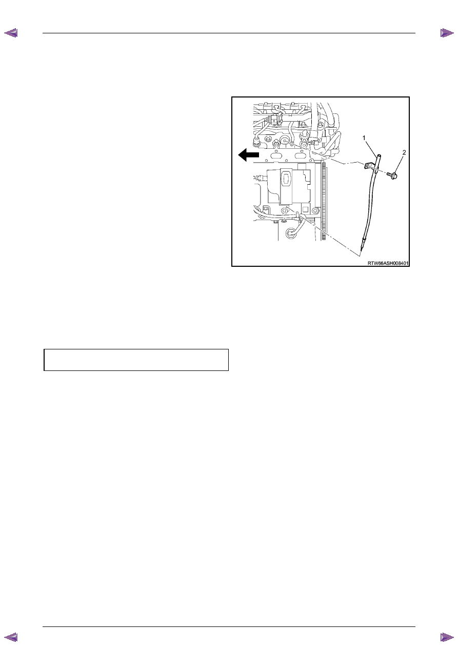
Oil Level Indicator Tube 

Remove 

Remove the oil level indicator from the oil level indicator tube. 

Remove the bolt (2) attaching the oil level indicator 
tube (1) and engine wiring harness retaining bracket. 

Withdraw the oil level indicator tube from the oil pan. 

Remove and discard the o-ring at the bottom of the oil 
level indicator tube. 

Figure 6A1 – 28 

Reinstall 

Reinstallation of the oil level indicator tube is the reverse of the removal procedure, noting the following: 

Install a new oil level indicator o-ring. 

Ensure the attaching bolt passes through the engine wiring harness retaining bracket. 

Tighten bolt to the correct torque specification. 

Oil level indicator tube attaching bolt 
torque specification ...................................8.0 – 12.0 Nm 


Engine Mechanical – V6 

Page 6A1–72 


Page 6A1–72 

3.5 

Accessory Drive Belt 

RWD Vehicle 

Remove 

Remove the air intake duct from between the air flow meter and the throttle body, refer to  

Section 6C1-3 Engine Management – V6 – Service Operations

Note the accessory drive belt (1) routing. 

Figure 6A1 – 29 

Using a suitable ½” drive socket bar (1), rotate the 
drive belt tensioner (2) clockwise, to reduce belt 
tension. 

While holding the tensioner in the reduced tension 
position, remove the accessory drive belt (3). 


N O T E  

If required use an assistant to maintain the 

tensioner in the required position. 

CAUTION


If running the engine with the accessory 
drive belt removed, the coolant pump will 
not be operating and the engine may 
overheat if left unsupervised even for a short 
period. 

Figure 6A1 – 30 

Engine Mechanical – V6 

Page 6A1–73 


Page 6A1–73 

Reinstall 

Install the drive belt over the A/C compressor, idler pulley, power steering pump, coolant pump, generator and 
tensioner pulleys. 

Using a suitable ½” drive socket bar (1), rotate the drive belt tensioner (2) clockwise, refer to Figure 6A1 – 30. 

With an assistant holding the tensioner in the required position, feed the accessory drive belt (3) over the 
crankshaft pulley. 

Slowly release the drive belt tensioner mechanism. 

N O T E  

Ensure the drive belt ribs are correctly aligned 
with the grooves in the accessory drive pulleys or 
damage to the drive belt and accessory drive 
components and pulleys may occur. 

Reinstall the air intake duct to the air flow meter and the throttle body, refer to 

Section 6C1-3 Engine Management 

– V6 – Service Operations

Run the engine to ensure correct operation. 

Engine Mechanical – V6 

Page 6A1–74 


Page 6A1–74 

3.6 

Accessory Drive Belt Idler Pulley 

Remove 

Remove the accessory drive belt, refer to 

3.5  Accessory Drive Belt

Remove the accessory drive belt idler pulley attaching 
bolt (1). 

Remove the dished washer (2) and accessory drive 
belt idler pulley (3). 


Figure 6A1 – 31 

Reinstall 

Reinstallation of the accessory drive belt idler pulley is the reverse of the removal procedure. Tighten the bolt to the 
correct torque specification. 

Accessory drive belt idler pulley  
attaching bolt torque specification......................50.0 Nm 


Content   ..  710  711  712  713   ..