Isuzu KB P190. Manual - part 711


  Index      Isuzu     Isuzu KB P190 - service repair manual 2007 year


Search            


Content   ..  709  710  711  712   ..


Isuzu KB P190. Manual - part 711


Engine Mechanical – V6 

Page 6A1–67 


Page 6A1–67 

Replace 

N O T E  

•  Quicker and more complete draining will 

occur if the engine oil is at normal operating 
temperature. However, care must be taken to 
avoid scalding from the hot oil. 

•  It recommended the oil filter be changed at 

each engine oil change, refer to 

3.2  Oil Filter

Remove the oil fill cap. 

To ensure complete draining of the oil pan, raise the front and rear of the vehicle to maintain a level attitude. If not 
using a hoist, support the vehicle with safety stands, refer to 

Section 0A General Information

Clean any foreign material from around the oil drain plug and place a suitable, clean drain tray under the engine. 


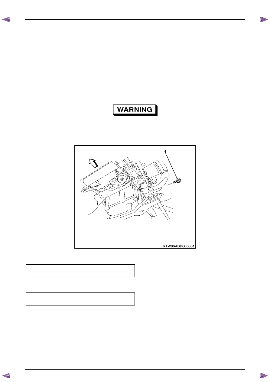
The oil may be hot. Avoid contact with the oil. 
Ensure that eyes and skin are protected. 

Remove the drain plug (1), taking care to avoid scalding from the hot oil. Allow the oil to drain. 

Clean and inspect the drain plug threads. If damaged, replace the drain plug. 


Figure 6A1 – 24 

Once the oil has completely drained, reinstall the drain plug and tighten to the correct torque specification. 

Oil pan drain plug 
torque specification ............................................25.0 Nm 

Replace the oil filter, refer to 

3.2  Oil Filter

Lower the vehicle to the ground and fill with the specified amount of SAE 5W30 lubricant. 

Engine Oil Capacity: 
With Oil Filter Change ........................................6.5 litres 

Install the oil fill cap. 

10 

Start the engine and check for leaks. 

Engine Mechanical – V6 

Page 6A1–68 


Page 6A1–68 

Pressure Check 

Run the engine to bring it to normal operating temperature. 

Park the vehicle on a level surface. A vehicle not level will affect the accuracy of the level reading. 

Stop the engine and wait 5 to 10 minutes to allow the oil to drain back into the oil pan. 

Check the oil level and top up with the recommended engine oil as required, refer to Check, in this Section. 

Remove the engine oil pressure sensor (1), refer to 

Section 6C1-3 Engine Management – V6 – Service 
Operations

Install the oil pressure gauge adaptor, Tool No. 
J36648-A into the oil pressure sender hole in the oil 
filter housing. 

Install a suitable oil pressure gauge into the adaptor. 

Start the engine. 

Measure and record the pressure reading on the 
gauge at idle and 2000 r.p.m. Compare the results 
with the specification. 

Minimum engine oil pressure  
@ idle................................................................... 69 kPa 

@ 2000 r.p.m. .................................................... 138 kPa 

10 

If the engine oil pressure is not to specification, refer to 

2.19  Engine Oil Pressure Diagnosis

11 

After completing the engine oil pressure check, stop 
the engine and remove the oil pressure gauge. 

Figure 6A1 – 25 

12 

Reinstall the oil pressure sensor, refer to 

Section 6C1-3 Engine Management – V6 – Service Operations

13 

Start the engine and check for leaks. 

Engine Mechanical – V6 

Page 6A1–69 


Page 6A1–69 

3.2 

Oil Filter Cartridge 

Replace 

N O T E  

•  The oil filter cartridge should be replaced at 

the correct time or distance intervals, refer to 

Section 0B Lubrication and Service

•  The oil filter cartridge should also be replaced 

whenever the engine oil is suspected to have 
been contaminated by foreign material. 

Remove and discard the oil filter cartridge (1). 

Install the new oil filter cartridge. 


Figure 6A1 – 26 

Engine Mechanical – V6 

Page 6A1–70 


Page 6A1–70 

3.3 

Oil Filter Adaptor 

Remove 


Disconnection of the battery affects 


certain vehicle electronic systems, refer to  

1.1   WARNING, CAUTION and NOTES

 before 

disconnecting the battery. 

Disconnect the battery negative terminal. 

Disconnect the wiring harness connector from the oil pressure sender. 


Remove the oil filter adaptor attaching bolts (2), four 
places. 

Remove the oil filter adaptor and discard the gasket 
(3). 

Clean the surfaces of the adaptor and cylinder block. 


•  Do not use a screwdriver or similar to 

prise the oil filter adapter from the engine 
as damage to the sealing surface may 
occur. 

•  If required, use a rubber mallet to tap the 

oil filter adapter to loosen the 
components prior to separating. 
Tapping should be done at bends, 
corners or reinforced areas to prevent 
distortion of parts. 

Figure 6A1 – 27 

Reinstall 

Reinstallation of the oil filter adaptor is the reverse of the removal procedure, noting the following: 

A new gasket must be used. 

Loosely install the oil filter adaptor attaching bolts, then tighten all fasteners to the correct torque specification. 

Oil filter adaptor attaching bolt 
torque specification ...................................20.0- 26.0 Nm 


Content   ..  709  710  711  712   ..