Isuzu KB P190. Manual - part 648


  Index      Isuzu     Isuzu KB P190 - service repair manual 2007 year


Search            


Content   ..  646  647  648  649   ..


Isuzu KB P190. Manual - part 648


Engine Mechanical – V6 

Page 6A1–113 


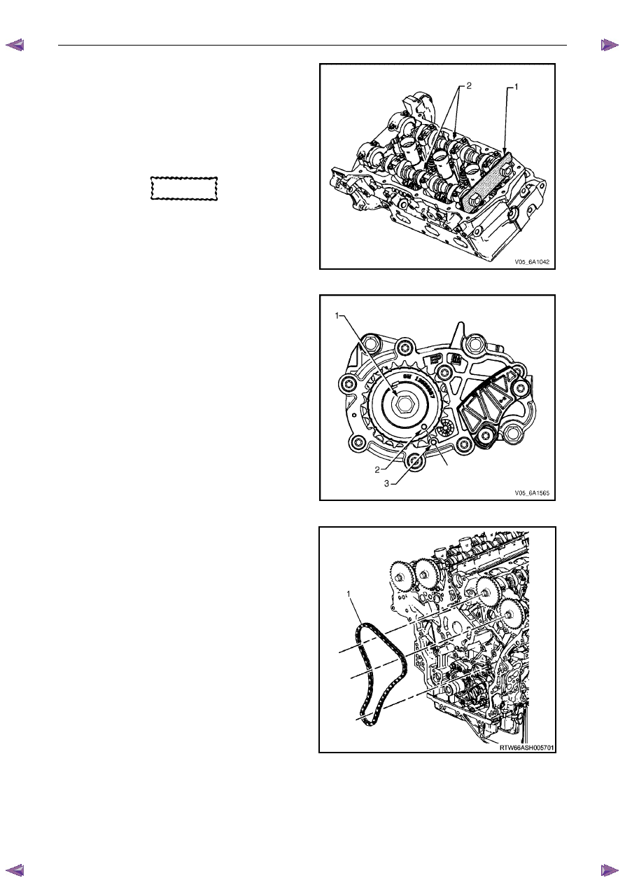
Install Tool No. EN 46105-1 (1) onto the rear of the 
left-hand cylinder head camshafts (2), and Tool No. 
EN 46105-2 onto the rear of the right-hand cylinder 
head camshafts. 

Ensure that Tool No. EN 46105 is fully seated onto 
the camshafts. 


CAUTION


All camshafts must be locked in place before 
installation of any timing chains. 

Figure 6A1 – 145 

Using Tool No. EN46111 (1), rotate the crankshaft in 
a clockwise direction until the crankshaft sprocket 
timing mark (2) is aligned with the indexing mark (3) 
on the oil pump housing. 

Figure 6A1 – 146 

Install the left-hand secondary timing chain (1) 
aligning the chain in the following manner: 


Figure 6A1 – 147 

Engine Mechanical – V6 

Page 6A1–114 


Wrap the secondary timing chain around both left-
hand camshaft drive sprockets. 

Ensure there are two bright links located on top of 
each of the camshaft actuator sprockets. 


Figure 6A1 – 148 

CAUTION


When aligning the left-hand secondary timing 
chain to the camshaft actuator sprockets, 
ensure the circular timing marks on the 
sprocket are used, NOT the triangular mark. 


Align the bright plated timing chain link (1) with the 
left-hand exhaust camshaft position actuator sprocket 
alignment circle mark (2). 


Figure 6A1– 153 

Engine Mechanical – V6 

Page 6A1–115 


10 

Align the bright plated timing chain link (1) with the 
intake camshaft position actuator sprocket alignment 
circle mark (2). 


Figure 6A1 – 149 

11 

Ensure the left-hand camshaft intermediate driveshaft 
sprocket is selected and orientated correctly. 


CAUTION


The left-hand camshaft intermediate 
driveshaft sprocket (1) is marked with the 
letters LB and ‘FRONT’, and the right-hand 
sprocket (2) is marked with the letters RB 
and 'FRONT' Ensure the correct sprocket is 
used and the 'FRONT' text is facing forwards 
when installed. 

Figure 6A1 – 150 

12 

Place the left-hand secondary timing chain around the 
left-hand camshaft intermediate driveshaft inner 
sprocket, with the bright plated timing chain link (1) 
aligned with the access hole (2) in the outer sprocket.


Figure 6A1 – 151 

Engine Mechanical – V6 

Page 6A1–116 


13 

Install the left-hand camshaft intermediate driveshaft 
sprocket to the cylinder block. 

14 

Install the driveshaft sprocket bolt (1) and tighten to 
the correct torque specification. 


Camshaft intermediate driveshaft sprocket 
attaching bolt torque specification...........58.0 – 72.0 Nm 

Figure 6A1 – 152 

15 

Verify the left-hand secondary timing chain timing 
mark alignments (1 to 6) 

Figure 6A1 – 153 

16 

Ensure the left-hand secondary timing chain guide is 
selected and orientated correctly. 


CAUTION


The left-hand secondary timing chain guide 
is marked with the letters LH. Ensure the 
correct shoe is used when installing to the 
left-hand side in this procedure and that the 
letters ‘LH” are facing the front of the vehicle 
when installed.  

Figure 6A1 – 154 


Content   ..  646  647  648  649   ..