Isuzu KB P190. Manual - part 646


  Index      Isuzu     Isuzu KB P190 - service repair manual 2007 year


Search            


Content   ..  644  645  646  647   ..


Isuzu KB P190. Manual - part 646


Engine Mechanical – V6 

Page 6A1–105 


11 

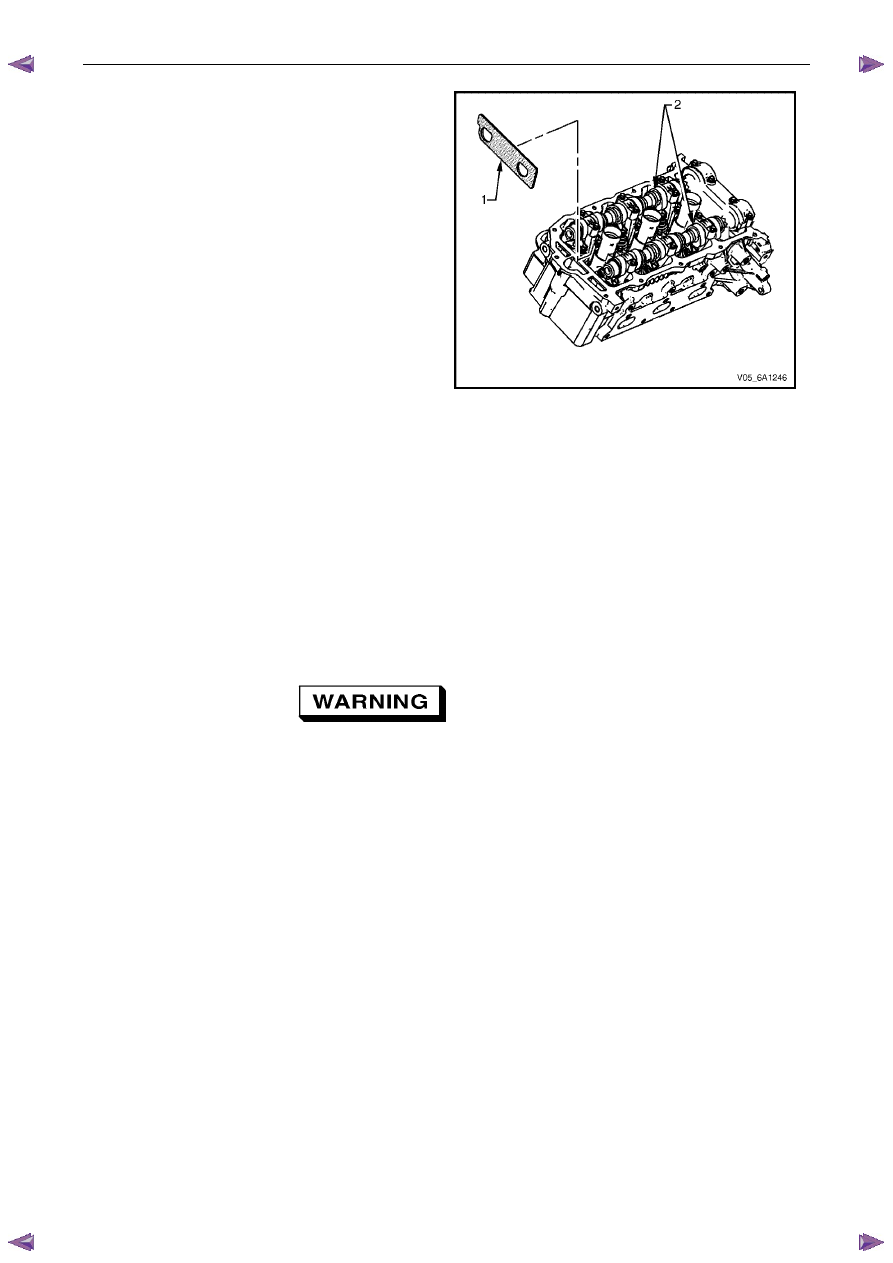
Remove Tool No. EN 46105-1 (1) from the right-hand 
cylinder head camshafts (2). 

Figure 6A1 – 127 

Clean 

Clean all the following components with a suitable solvent: 
• 

crankshaft sprocket, 

• 

primary timing chain, 

• 

primary timing chain guide, 

• 

primary timing chain tensioner, 

• 

secondary timing chains, 

• 

secondary timing chain shoes, 

• 

secondary timing chain guides, 

• 

secondary timing chain tensioners, and 

• 

bolts. 


Safety glasses must be worn when using 
compressed air. 

Dry all the components with compressed air. 

Engine Mechanical – V6 

Page 6A1–106 


Inspect 

Timing Chains 

Inspect the primary and/or secondary timing chains 
for the following: 
• 

binding or worn rollers (1), 

• 

loose links (2), and 

• 

loose pins (3). 

Replace a damaged timing chain as required. 


Figure 6A1 – 128 

Camshaft Intermediate Driveshaft Sprockets 


Figure 6A1 – 129 

Inspect the camshaft intermediate driveshaft sprockets for the following: 
• 

Damage to the primary and secondary timing chain sprocket (1), refer to Figure 6A1 – 129. 

• 

Damage to the hub bearing (2). Ensure the hub bearing spins freely. If the hub bearing wobbles, is noisy or 
feels rough when rotated replace the camshaft intermediate sprocket, and 

• 

Damage to the bolt flange seating / sealing surface (3). 

• 

Damage to the bearing hub-to-engine block sealing surface. 

Inlet and Exhaust Camshaft Sprocket 

Inspect the camshaft sprocket assemblies, refer to 3.18 

Camshaft Sprocket. 

Engine Mechanical – V6 

Page 6A1–107 


Crankshaft Sprocket 

Inspect the crankshaft sprocket for the following: 
• 

sprocket damage (1), 

• 

bore damage (2), 

• 

keyway damage (3), and 

• 

damage to the cushion material (4). 

Replace a damaged sprocket as required. 


Figure 6A1 – 130 

Primary Timing Chain Upper Guide 

Inspect the primary timing chain upper guide for the 
following: 
• 

worn guide surface (1), 

• 

cracked or broken guide surface (2), and 

• 

cracked or damaged guide base (3). 

Replace a damaged guide as required. 

Figure 6A1 – 131 

Primary Timing Chain Lower Guide 

Inspect the primary timing chain lower guide for the 
following: 
• 

worn guide surface (1), 

• 

cracked or broken guide surface (2), and 

• 

cracked or damaged guide base (3). 

Replace the primary timing chain lower guide by 
replacing the oil pump assembly, refer to 3.17  Oil 
Pump Assembly. 


N O T E  

The primary timing chain lower guide is not 
serviced separately and is part of the oil pump 
assembly. 

Figure 6A1 – 132 

Engine Mechanical – V6 

Page 6A1–108 


Primary Timing Chain Tensioner 


Figure 6A1 – 133 

Inspect the primary timing chain tensioner for worn shoe surface (1), refer to Figure 6A1 – 133. 

Inspect the tensioner for a locked or binding tensioner shaft (2). Reset the plunger (3) and ensure the tensioner 
shaft moves freely in and out of the body of the tensioner. 

N O T E  

To reset the tensioner, use a suitably sized flat 
blade screwdriver or Tool No. J 45027 (4) to wind 
the plunger in a clockwise direction, into the 
tensioner shaft. 

Replace a damaged tensioner as required. 

Left-hand Secondary Timing Chain Guide 

Inspect the left-hand secondary timing chain guide for 
the following: 
• 

worn guide surface (1), 

• 

cracked or broken guide surface (2), and 

• 

cracked or damaged guide base (3). 

Replace a damaged guide as required. 


Figure 6A1 – 134 


Content   ..  644  645  646  647   ..