Isuzu KB P190. Manual - part 642


  Index      Isuzu     Isuzu KB P190 - service repair manual 2007 year


Search            


Content   ..  640  641  642  643   ..


Isuzu KB P190. Manual - part 642


Engine Mechanical – V6 

Page 6A1–89 


11 

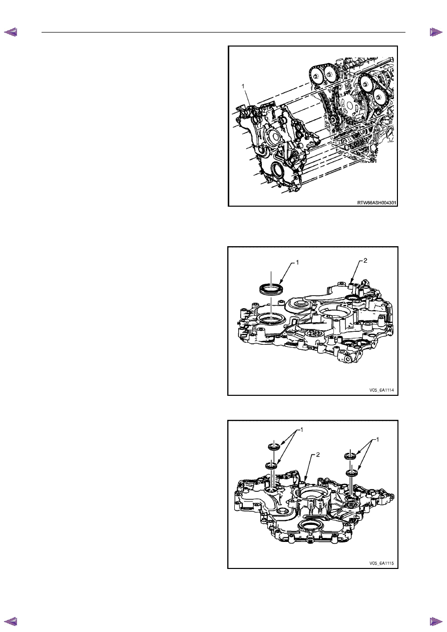
Remove the front cover assembly (1). 

Figure 6A1 – 85 

Disassemble 

Remove the crankshaft front oil seal (1) from the 
engine front cover (2) using a flat bladed tool or seal 
remover, Tool No. E-308. Discard the seal. 

Figure 6A1 – 86 

Remove the camshaft position actuator valve oil 
seals (1) from the engine front cover (2). Discard the 
seals. 

Figure 6A1 – 87 

Engine Mechanical – V6 

Page 6A1–90 


Remove the coolant pump seal (1) from the engine 
front cover (2). Discard the seal. 

Figure 6A1 – 88 

Clean 

Remove any RTV sealant (1) from the engine front 
cover using a plastic or wood scraper. 

CAUTION


•  Insert a piece of cardboard between the 

front of the oil pan and oil pump to 
prevent any contaminants from falling 
into the oil pan. 

•  Do not use a sharp or metal gasket 

scraper to clean the sealing surfaces. 

Clean out any debris from the bolt holes. 

Clean the front cover with a suitable cleaning solvent.

Dry the front cover with compressed air. 


Safety glasses must be worn when using 
compressed air. 

Figure 6A1 – 89 

Use compressed air to remove any engine coolant from the engine cooling passages and from the top of the oil 
pan oil deflector. 

Engine Mechanical – V6 

Page 6A1–91 


Inspect 

Inspect both sides of the engine front cover for the 
following conditions: 
• 

damage to the camshaft position actuator valve 
oil seal bores (1), 

• 

damage to the bolt holes (2), 

• 

damage and/or corrosion to the engine coolant 
passage (3), 

• 

dents or damage to the exterior (4), 

• 

damage to the crankshaft front oil seal bore (5),

• 

gouges or damage to the coolant pump sealing 
surfaces (6), and 

• 

damage to the coolant pump bolt hole 
threads (7). 

Repair or replace the front cover as required. 

Figure 6A1 – 90 

Reassemble 

Install a new crankshaft front oil seal (1) into the front 
cover (2) using crankshaft front seal installer, Tool 
No. J-29184 (3) and a suitable hammer. 


CAUTION


Do not lubricate the crankshaft front oil seal 
or crankshaft balancer sealing surfaces. The 
crankshaft balancer is installed into a dry 
seal. 

Figure 6A1 – 91 

Install a new camshaft position actuator valve oil seal 
(1) into the front cover (2) using Tool No. EN-46103 
(3) and a suitable hammer. 


Figure 6A1 – 92 

Engine Mechanical – V6 

Page 6A1–92 


Reinstall 

Reinstallation of the front cover is the reverse of the removal procedure, noting the following: 

Install the guide pins, Tool No. EN-46109 (1) into the 
engine block, two places. 

Figure 6A1 – 93 

Install a new engine front cover to cylinder block 
seal (1). 

Figure 6A1 – 94 

Apply a 3 mm bead of RTV sealant (1) to the front 
cover. 

Figure 6A1 – 95 


Content   ..  640  641  642  643   ..