Isuzu KB P190. Manual - part 640


  Index      Isuzu     Isuzu KB P190 - service repair manual 2007 year


Search            


Content   ..  638  639  640  641   ..


Isuzu KB P190. Manual - part 640


Engine Mechanical – V6 

Page 6A1–81 


14 

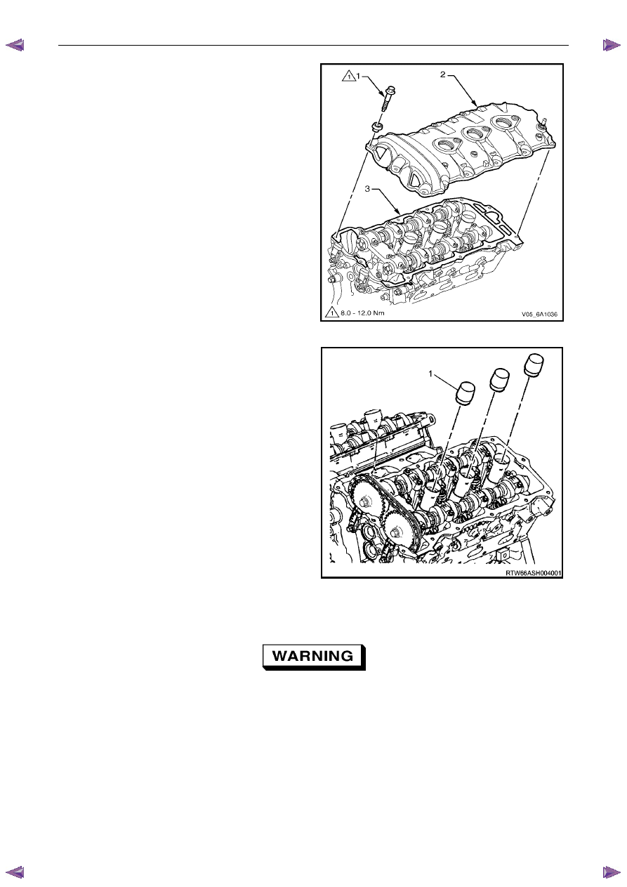
Remove the bolt (1), 13 places, attaching the camshaft 
cover (2) to the cylinder head (3). 

15 

Remove the cover and discard the seal. 

Figure 6A1 – 66 

16 

Install Tool No. EN-46101 (1) to the spark plug tubes 
of the cylinder head to prevent entry of dirt into the 
combustion chamber. 

Figure 6A1 – 67 

Clean and Inspect 


Safety glasses must be worn when using 
compressed air. 

Clean the camshaft cover with suitable cleaning solvent and blow dry with compressed air.  

Inspect the cover for cracking and distortion.  

Check the spark plug tube seals for damage.  

If the camshaft cover is damaged in any way that will affect it’s performance to seal and stop the ingress of dirt, 
replace the camshaft cover. 

Reinstall 

Reinstallation of the camshaft cover assembly is the reverse of the removal procedure, noting the following: 

Engine Mechanical – V6 

Page 6A1–82 


If not already fitted, install Tool No. EN-46101 (1) to 
the spark plug tubes of the cylinder head. 

Figure 6A1 – 68 

Ensure that the grommet (1), 13 places, is correctly 
seated in its hole. 

Wipe the camshaft cover sealing surface on the 
cylinder head with a clean lint free cloth. 

Figure 6A1 – 69 

Ensure that a new seal is correctly fitted to the 
camshaft cover. Place a 3 mm bead of RTV sealant on 
the join line of the engine front cover (1). 


Figure 6A1 – 70 

Engine Mechanical – V6 

Page 6A1–83 


Place the camshaft cover (1) into position onto the 
cylinder head (2).  

Figure 6A1 – 71 

Loosely install the camshaft cover bolt (1), 13 places.

Figure 6A1 – 72 

Tighten the camshaft cover bolts to the correct torque 
specification, in the sequence shown. 


Camshaft cover attaching bolt 
torque specification ...................................8.0 – 12.0 Nm 


Figure 6A1 – 73 

Engine Mechanical – V6 

Page 6A1–84 


Remove Tool No. EN-46101 (1). 

Tighten all remaining fasteners to the correct torque 
specification. 


Engine ground connector bolt  
torque specification ............................................10.0 Nm 

Engine wiring harness former attaching 
bolt torque specification ..........................12.0 – 16.0 Nm 


Figure 6A1 – 74 

3.13  Crankshaft Balancer Assembly 

Remove 

Remove the accessory drive belt, refer to 3.5 

Accessory Drive Belt. 

Remove the starter motor, refer to 6D1-2_ Starting System. 

Install Tool No. EN-46106 (1) into the starter motor 
opening to stop the camshaft from rotating. 

Figure 6A1 – 75 


Content   ..  638  639  640  641   ..