Isuzu KB P190. Manual - part 639


  Index      Isuzu     Isuzu KB P190 - service repair manual 2007 year


Search            


Content   ..  637  638  639  640   ..


Isuzu KB P190. Manual - part 639


Engine Mechanical – V6 

Page 6A1–77 


12 

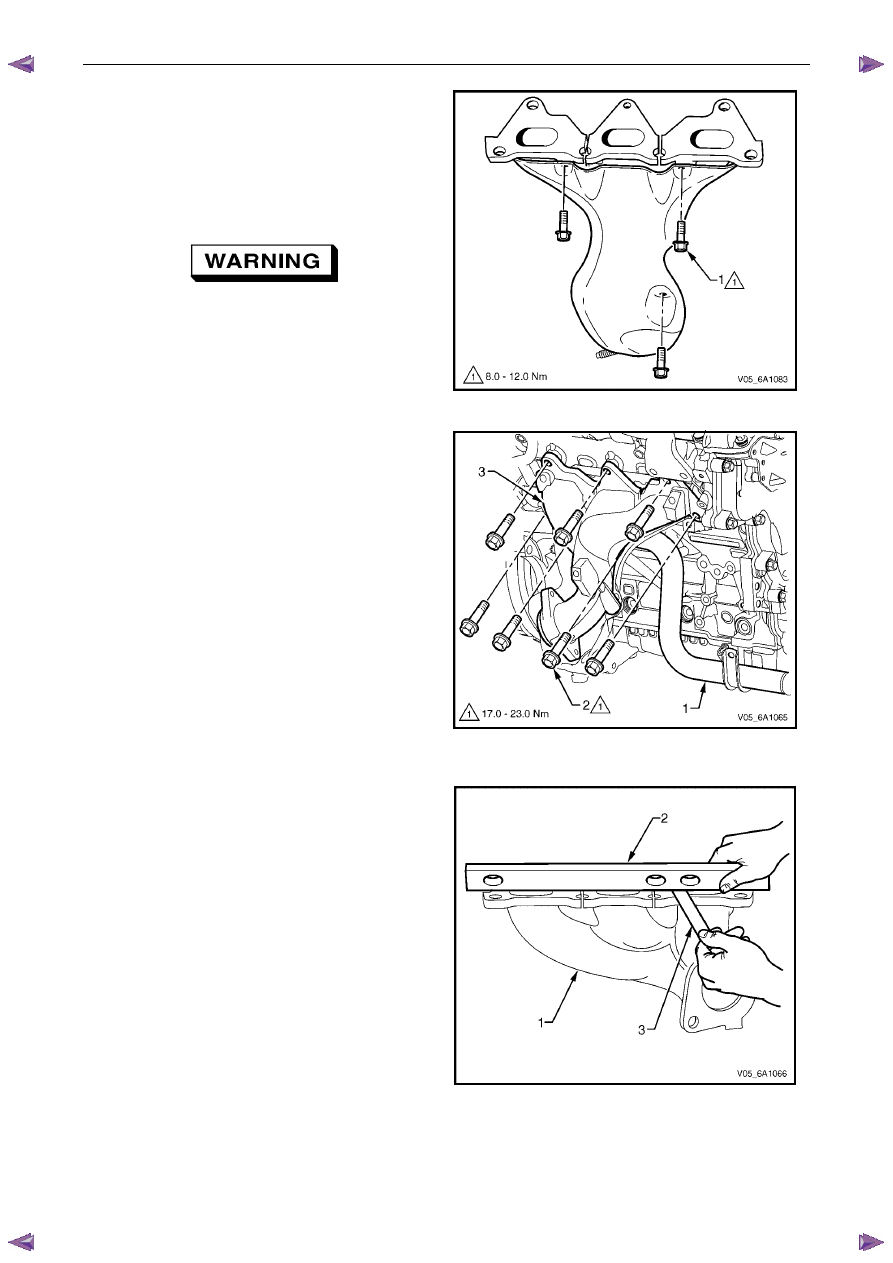
Remove the three bolts (1), attaching the exhaust 
manifold inner heat shield to the exhaust manifold. 


13 

Using a suitable commercially available non-corrosive 
cleaning solvent and a soft bristled parts cleaning 
brush, thoroughly clean the exhaust manifold. 

14 

Dry the exhaust manifold using compressed air. 


Safety glasses must be worn when using 
compressed air. 

Figure 6A1 – 59 

N O T E  

•  The same procedure applies to the Right-

hand exhaust manifold. 


•  To gain access to the lower rear exhaust 

manifold attaching bolts (2), apply a slight 
downward movement to the coolant inlet 
pipe (1). 


Inspect 

Inspect the exhaust manifold (1) for the following: 
• 

Damage to the threaded holes for the heat shield 
mounting. 

• 

Damage to the exhaust manifold mounting holes. 

• 

Damage to the threads of the exhaust manifold to 
exhaust pipe flange studs. 

• 

Damage to the gasket sealing surfaces. 

• 

Using a straight edge (2) and feeler gauges (3), check 
the cylinder head mounting face of the exhaust 
manifold does not exceed the maximum distortion 
specification of 0.25mm. 

N O T E  

If the surface flatness is not within 
specifications, the exhaust manifold is warped 
and must be replaced. 

Figure 6A1 – 60 

Reinstall 

Reinstallation of the exhaust manifold assembly is the reverse of the removal procedure, noting the following: 

Ensure the exhaust manifold, cylinder head and exhaust pipe flange surfaces are clean. 

Engine Mechanical – V6 

Page 6A1–78 


Position a new exhaust manifold gasket onto the exhaust manifold. 

Apply a 5 mm bead of Loctite 272 thread sealant (or equivalent) to the threads of the exhaust manifold attaching 
bolts. 

Install the bolts into the exhaust manifold. This will prevent the gasket from falling off the manifold. 

Manoeuvre the exhaust manifold into position and install the exhaust manifold attaching bolts. 

From underneath the vehicle install the exhaust manifold to exhaust pipe flange nuts. 

Tighten the exhaust manifold attaching bolts to the correct torque specification. 

N O T E  

When tightening the exhaust manifold to cylinder 
head attaching bolts, begin with the centre bolts, 
then alternate from side to side to the outer bolts. 

Exhaust manifold to cylinder head 
attaching bolt torque specification...........17.0 – 23.0 Nm 

Apply an anti seize compound such as Caltex Kopr-Kote (or equivalent) to the cleaned heat shield bolt threads. 
Install the heat shield attaching bolts and tighten to the correct torque specification. 

Exhaust manifold heat shield attaching  
bolt torque specification ............................8.0 – 12.0 Nm 

For the right-hand side, install the battery harness ground cable attaching nut through the ground terminal and 
lower coolant tube mounting lug, and tighten to the correct torque specification. 

Battery harness ground terminal 
attaching nut torque specification.......................13.0 Nm 

Engine Mechanical – V6 

Page 6A1–79 


3.12 Camshaft 

Cover 

Remove 

Remove the intake manifold assembly, refer to 3.10 

Intake Manifold Assembly – Complete. 

For the left-hand side, remove the evaporative (EVAP) emission canister purge solenoid, refer to 6C1-3 Engine 
Management – V6 – Service Operations. 

Remove the two bolts (1) attaching the engine wiring 
harness former to the rear of the cylinder heads. 

Unclip the transmission vent tube (2) from the engine 
wiring harness. 

Figure 6A1 – 61 

Disconnect the oxygen sensor wiring harness 
connector (1) from the engine wiring harness (2), left-
hand shown, right-hand similar. 

Figure 6A1 – 62 

Engine Mechanical – V6 

Page 6A1–80 


Remove the bolt (1) attaching the ground connector 
(2) to the cylinder head. 

Fro the left-hand side, disconnect the engine coolant 
temperature (ECT) sensor wiring connector (3). 

Unclip the engine wiring harness retaining lugs from 
the side of the camshaft cover. 

Figure 6A1 – 63 

For the right-hand side, remove the engine wiring 
harness retaining clip (1) from the engine control 
module (ECM) bracket (2). 

Figure 6A1 – 64 

10 

Disconnect the camshaft position (CMP) sensor wiring 
connector (1). 

11 

Unclip the engine wiring harness retaining lug (3) from 
the front of the camshaft cover. 

12 

Remove the ignition coil assemblies; refer to 6C1-3 
Engine Management – V6 – Service Operations. 

13 

Move the engine wiring harness clear of the camshaft 
cover. 


Figure 6A1 – 65 


Content   ..  637  638  639  640   ..