Isuzu KB P190. Manual - part 555


  Index      Isuzu     Isuzu KB P190 - service repair manual 2007 year


Search            


Content   ..  553  554  555  556   ..


Isuzu KB P190. Manual - part 555


6E–50

ENGINE DRIVEABILITY AND EMISSIONS

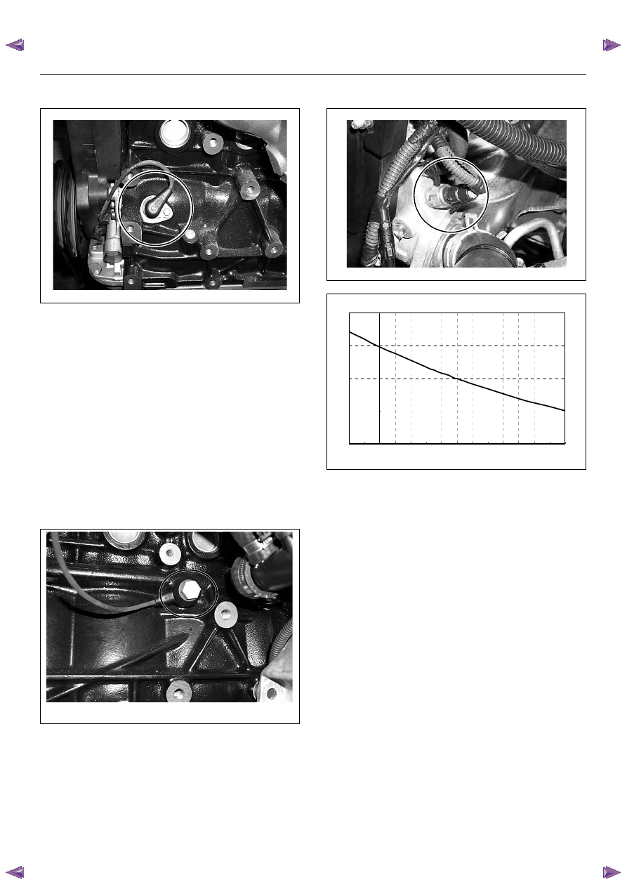
Crankshaft Position (CKP) Sensor

The crankshaft position (CKP) sensor, which sends a
signal necessary for deciding on injection timing to the
ECM, is mounted on the left-hand side of the cylinder
block just back of the A/C compressor.
The crankshaft has a 58 teeth press-fit timing disc, from
which the CKP sensor reads the position of the
crankshaft at all the times. It converts this to an
electrical signal, which it sends to the ECM. 
Using the 58 X signals per rotation and the timing-mark
signal sent by the CKP sensor, the ECM is able to
accurately calculate engine speed and crank position.
The ECM converts the 58 X signals into square signals.
This converted signal is sent from the ECM terminal J2-
25 to the tachometer.

Knock Sensor (KS)

The knock sensor (KS) contains an element that
converts detection of knock into an electrical signal, and
is mounted on cylinder block wall. 
When the ECM receives a signal that indicates knock,
the ECM orders ignition timing to be adjusted to
compensate.

Engine Coolant Temperature (ECT) Sensor

The ECT sensor is a thermistor. A temperature changes
the resistance value. And it changes voltage. In other
words it measures a temperature value. It is installed on
the coolant stream. Low coolant temperature produces
a high resistance.
The ECM supplies 5 volts signal to the ECT sensor
through resisters in the ECM and measures the voltage.
The signal voltage will be high when the engine
temperature is cold, and it will be low when the engine
temperature is hot.


Characteristic of  ECT Sensor -Ref erence-

10

100

1000

10000

100000

-20

-10

0

10

20

30

40

50

60

70

80

90

100

110

120

Coolant Temp. (deg. C) (Tech2 Reading)

R

e

si

st

ance (

ohm

) (

S

ol

id

 Li

ne)

ENGINE DRIVEABILITY AND EMISSIONS

6E–51

Intake Air Temperature (IAT) Sensor

The IAT sensor is a thermistor. A temperature changes
the resistance value. And it changes voltage. In other
words it measures a temperature value. Low air
temperature produces a high resistance.
The ECM supplies 5 volts signal to the IAT sensor
through resisters in the ECM and measures the voltage.
The signal voltage will be high when the air temperature
is cold, and it will be low when the air temperature is
hot.

Vehicle Speed Sensor (VSS)

The VSS is a magnet rotated by the transmission output
shaft. The VSS uses a hall element. It interacts with the
magnetic field treated by the rotating magnet. It outputs
pulse signal. The 12 volts operating supply from the
meter fuse.

Heated Oxygen (O

2

) Sensor

The heated oxygen sensor consists of a 4-wire low
temperature activated zirconia oxygen analyzer element
with heater for operating temperature of 315°C, and
there is one mounted on each exhaust pipe. 
A constant 450millivolt is supplied by the ECM between
the two supply terminals, and oxygen concentration in
the exhaust gas is reported to the ECM as returned
signal voltage.
The oxygen present in the exhaust gas reacts with the
sensor to produce a voltage output. This voltage should
constantly fluctuate from approximately 100mV to
1000mV and the ECM calculates the pulse width
commanded for the injectors to produce the proper
combustion chamber mixture.
Low oxygen sensor output voltage is a lean mixture
which will result in a rich commanded to compensate.
High oxygen sensor output voltage is a rich mixture
which result in a lean commanded to compensate.
When the engine is first started the system is in “Open
Loop” operation. In “Open Loop”, the ECM ignores the
signal from the oxygen sensors. When various
conditions (ECT, time from start, engine speed &
oxygen sensor output) are met, the system enters
“Closed Loop” operation. In “Closed Loop”, the ECM
calculates the air fuel ratio based on the signal from the
oxygen sensors.
Heated oxygen sensors are used to minimize the
amount of time required for closed loop fuel control to
begin operation and allow accurate catalyst monitoring. 
The oxygen sensor heater greatly decreases the
amount of time required for fuel control sensors to
become active.
Oxygen sensor heaters are required by catalyst monitor
and sensors to maintain a sufficiently high temperature
which allows accurate exhaust oxygen content readings
further away from the engine.

Characteristic of  IAT Sensor -Ref erence-

10

100

1000

10000

100000

-20

-10

0

10

20

30

40

50

60

70

80

90

100

110

120

Intake Air Temp. (deg. C) (Tech2 Reading)

Resi

st

ance (

ohm

) (

S

ol

id Li

ne)

6E–52

ENGINE DRIVEABILITY AND EMISSIONS

GENERAL DESCRIPTION FOR FUEL 
METERING

The fuel metering system starts with the fuel in the fuel
tank. An electric fuel pump, located in the fuel tank,
pumps fuel to the fuel rail through an in-line fuel filter.
The pump is designed to provide fuel at a pressure
above the pressure needed by the injectors.
A fuel pressure regulator in the fuel rail keeps fuel
available to the fuel injectors at a constant pressure.
A return line delivers unused fuel back to the fuel tank.
The basic function of the air/fuel metering system is to
control the air/fuel delivery to the engine. Fuel is
delivered to the engine by individual fuel injectors
mounted in the intake manifold.
The main control sensor is the heated oxygen sensor
located in the exhaust system. The heated oxygen
sensor reports to the ECM how much oxygen is in the
exhaust gas. The ECM changes the air/fuel ratio to the
engine by controlling the amount of time that fuel
injector is “On”.
The best mixture to minimize exhaust emissions is 14.7
parts of air to 1 part of gasoline by weight, which allows
the catalytic converter to operate most efficiently.
Because of the constant measuring and adjusting of the
air/fuel ratio, the fuel injection system is called a “closed
loop” system.
The ECM monitors signals from several sensors in
order to determine the fuel needs of the engine. Fuel is
delivered under one of several conditions called “mode”.
All modes are controlled by the ECM.

Battery Voltage Correction Mode

When battery voltage is low, the ECM will compensate
for the weak spark by increasing the following:

• The amount of fuel delivered.

• The idle RPM.

Clear Flood Mode

Clear a flooded engine by pushing the accelerator pedal
down all the way. The ECM then de-energizes the fuel
injectors. The ECM holds the fuel injectors de-energized
as long as the throttle remains above 75% and the
engine speed is below 800 RPM. If the throttle position
becomes less than 75%, the ECM again begins to pulse
the injectors ON and OFF, allowing fuel into the
cylinders.

Deceleration Fuel Cutoff (DFCO) Mode

The ECM reduces the amount of fuel injected when it
detects a decrease in the throttle position and the air
flow. When deceleration is very fast, the ECM may cut
off fuel completely. Until enable conditions meet the
engine revolution less 1000 rpm or manifold absolute
pressure less than 10 kPa.

Engine Speed/ Vehicle Speed/ Fuel Disable 
Mode 

The ECM monitors engine speed. It turns off the fuel
injectors when the engine speed increases above 6000
RPM. The fuel injectors are turned back on when
engine speed decreases below 3500 RPM.

Acceleration Mode

The ECM provides extra fuel when it detects a rapid
increase in the throttle position and the air flow.

Fuel Cutoff Mode

No fuel is delivered by the fuel injectors when the
ignition is OFF. This prevents engine run-on. In addition,
the ECM suspends fuel delivery if no reference pulses
are detected (engine not running) to prevent engine
flooding.

Starting Mode

When the ignition is first turned ON, the ECM energizes
the fuel pump relay for two seconds to allow the fuel
pump to build up pressure. The ECM then checks the
engine coolant temperature (ECT) sensor and the
throttle position sensor to determine the proper air/fuel
ratio for starting.
The ECM controls the amount of fuel delivered in the
starting mode by adjusting how long the fuel injectors
are energized by pulsing the injectors for very short
times.

Run Mode

The run mode has the following two conditions:

• Open loop

• Closed loop
When the engine is first started, the system is in  “open
loop” operation. In  “Open Loop,” the ECM ignores the
signal from the heated oxygen sensor (HO2S). It
calculates the air/fuel ratio based on inputs from the TP,
ECT, and MAP sensors.
The system remains in  “Open Loop” until the following
conditions are met:

• The HO2S has a varying voltage output showing that

it is hot enough to operate properly (this depends on
temperature).

• The ECT has reached a specified temperature.

• A specific amount of time has elapsed since starting

the engine.

• Engine speed has been greater than a specified RPM

since start-up.

The specific values for the above conditions vary with
different engines and are stored in the programmable
read only memory (PROM). When these conditions are
met, the system enters  “closed loop” operation. In
“closed loop,” the ECM calculates the air/fuel ratio
(injector on-time) based on the signal from the HO2S.
This allows the air/fuel ratio to stay very close to 14.7:1.

ENGINE DRIVEABILITY AND EMISSIONS

6E–53

Fuel Metering System Components

The fuel  metering system is made up of the following
parts.

• Fuel injector

• Throttle body

• Fuel  rail

• Fuel pressure regulator

• ECM

• Crankshaft position (CKP) sensor

• Idle air control (IAC) valve

• Fuel  pump

Fuel Injector

The group fuel injection fuel injector is a solenoid
operated device controlled by the ECM. The ECM
energizes the solenoid, which opens a valve to allow
fuel delivery.
The fuel is injected under pressure in a conical spray
pattern at the opening of the intake valve. Excess fuel
not used by the injectors passes through the fuel
pressure regulator before being returned to the fuel
tank.

Fuel Pressure Regulator 

The fuel pressure regulator is a diaphragm-operated
relief valve mounted on the fuel rail with fuel pump
pressure on one side and manifold pressure on the
other side. The fuel pressure regulator maintains the
fuel pressure available to the injector at three times
barometric pressure adjusted for engine load. It may be
serviced separately.
If the pressure is too low or poor performance, DTC
P0131 or P1171 will be the result. If the pressure is too
high, DTC P0132 or P1167 will be the result. Refer to
Fuel System Diagnosis for information on diagnosing
fuel pressure conditions.

Fuel Rail

The fuel rail is mounted to the top of the engine and
distributes fuel to the individual injectors. Fuel is
delivered to the fuel inlet tube of the fuel rail by the fuel
lines. The fuel goes through the fuel rail to the fuel
pressure regulator. The fuel pressure regulator
maintains a constant fuel pressure at the injectors.
Remaining fuel is then returned to the fuel tank.

Fuel Pump Electrical Circuit

When the key is first turned ON, the ECM energizes the
fuel pump relay for two seconds to build up the fuel
pressure quickly. If the engine is not started within two
seconds, the ECM shuts the fuel pump off and waits
until the engine is cranked. When the engine is cranked
and the 58X crankshaft position signal has been
detected by the ECM, the ECM supplies 12 volts to the
fuel pump relay to energize the electric in-tank fuel
pump.
An inoperative fuel pump will cause a  “no-start”
condition. A fuel pump which does not provide enough

pressure will result in poor performance.

Thottle Body Unit

The throttle body has a throttle plate to control the
amount of air delivered to the engine. The Thottle
position sensor and IAC valve are also mounted on the
throttle body.
Vacuum ports located behind the throttle plate provide
the vacuum signals needed by various components.
Engine coolant is directed through a coolant cavity in
the throttle body to warm the throttle valve and to
prevent icing.


Content   ..  553  554  555  556   ..