Isuzu KB P190. Manual - part 518
6A-58 ENGINE MECHANICAL (C24SE)
Clean
Plastigage from journals.
Lightly coat journals and bearings with engine oil.
Installation
Install bearing cap and shell using new bolts.
Torque - Angle Method
Main bearing cap bolt - 60 N
⋅m (6.1 kgf⋅m) +40° to 50°.
Con-rod bearing cap bolts - 35 N
⋅m (3.9 kgf⋅m) +45°.
2.Micrometer and gauge method.
Crankshaft removed.
Installation
1. Install caps and bearing shells to con-rods and cylinder
block.
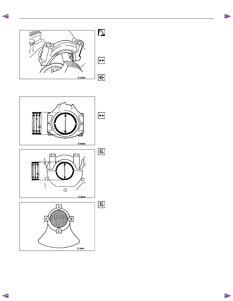
Measure
Con-rod and main bearing diameters at three points I, II, III
(arrowed).
Divide the sum of the three measurements by three to obtain a
mean diameter.
The top illustration shows con-rod measuring points.
The second illustration shows main bearing measuring points.
Measure
Crankshaft main and con-rod bearing journals at points I and
II. Divide the sum of both measurements to obtain a mean
diameter.
Crankshaft must be replaced if mean diameter of main or con-
rod journals is below specified limit - see "Technical Data".
If crankshaft is serviceable subtract crankshaft mean journal
diameters from corresponding shell bearing mean diameters to
determine bearing clearance.
Permissible main bearing clearance - 0.015 to 0.04mm/0.0006
to 0.002in.
Permissible con-rod bearing clearance - 0.006 to
0.031mm/0.002 to 0.001in.