Isuzu KB P190. Manual - part 517
6A-54 ENGINE MECHANICAL (C24SE)
RTW46ASH002401
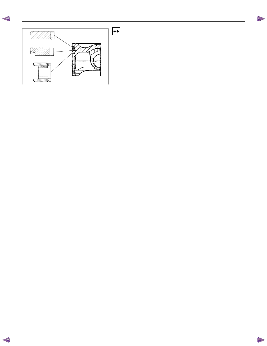
Installation
1. Install oil scraper ring.
2. Offset ring gaps of steel band rings each 25 to 50 mm/1
to 2in. to the left or right of the intermediate ring gap.
3. Install piston rings.
4. Offset ring gaps by approx. 180
°.
5. Install second piston ring with identification mark "TOP"
facing upwards.
6. Install piston with con-rod according to the corresponding
operation.