Isuzu KB P190. Manual - part 208
ENGINE MECHANICAL 6A – 27
111R300001
COOLING SYSTEM
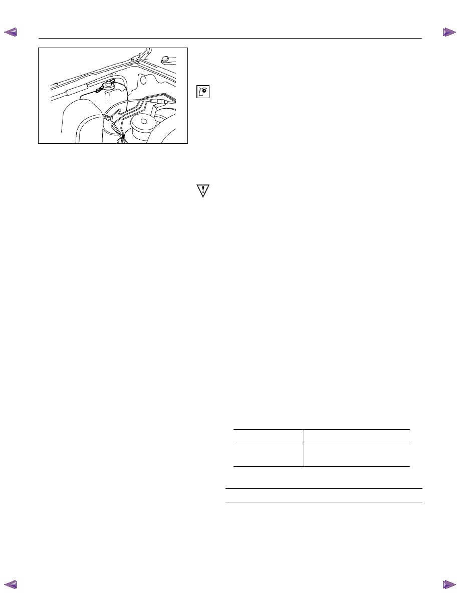
Coolant Level
Check the coolant level and replenish the radiator reserve
tank as necessary.
If the coolant level falls below the “MIN” line, carefully
check the cooling system for leakage. Then add enough
coolant to bring the level up to the “MAX” line.
Engine coolant Filling up procedure
1. Make sure that the engine is cool.
Warning:
When the coolant is heated to a high temperature, be
sure not to loosen or remove the rediator cap.
Otherwise you might get scalded by hot vapor or
boiling water.
To open the radiator cap, put a piece of thick cloth on
the cap and loosen the cap slowly to reduce the
pressure when the coolant has become cooler.
2. Open rediator cap pour coolant up to filler neck
3. Pour coolant into reservoir tank up to “MAX” line
4. Tighten radiator cap and start the engine. After idling
for 2 to 3 minutes, stop the engine and reopen radiator
cap. If the water level is lower, replenish.
5. After replenish the coolant tighten radiator cap, warm
up the engine at about 2000 rpm. Set heater
adjustment to the highest temperature position, and let
the coolant circulate also into heater water system.
6. Check to see the thermometer, continuously idling 5
minutes and stop the engine.
7. When the engine has been cooled, check filler neck
for water level and replenish if required. Should
extreme shortage of coolant is found, check the
coolant system and reservoir tank hose for leakage.
8. Pour coolant into the reservoir tank up to “MAX” line.
Engine Coolant Total Capacity
Lit (U.S / UK gal)
4JA1 / TC
9.4 (2.5 / 2.1)
4JH1TC
M/T: 10.1 (2.7 / 2.2)
A/T: 10.0 (2.6 / 2.2)
Mixing Ratio (Anti-Freeze Solution/Water)
50 %