Isuzu KB P190. Manual - part 1464


  Index      Isuzu     Isuzu KB P190 - service repair manual 2007 year


Search            


Content   ..  1462  1463  1464  1465   ..


Isuzu KB P190. Manual - part 1464


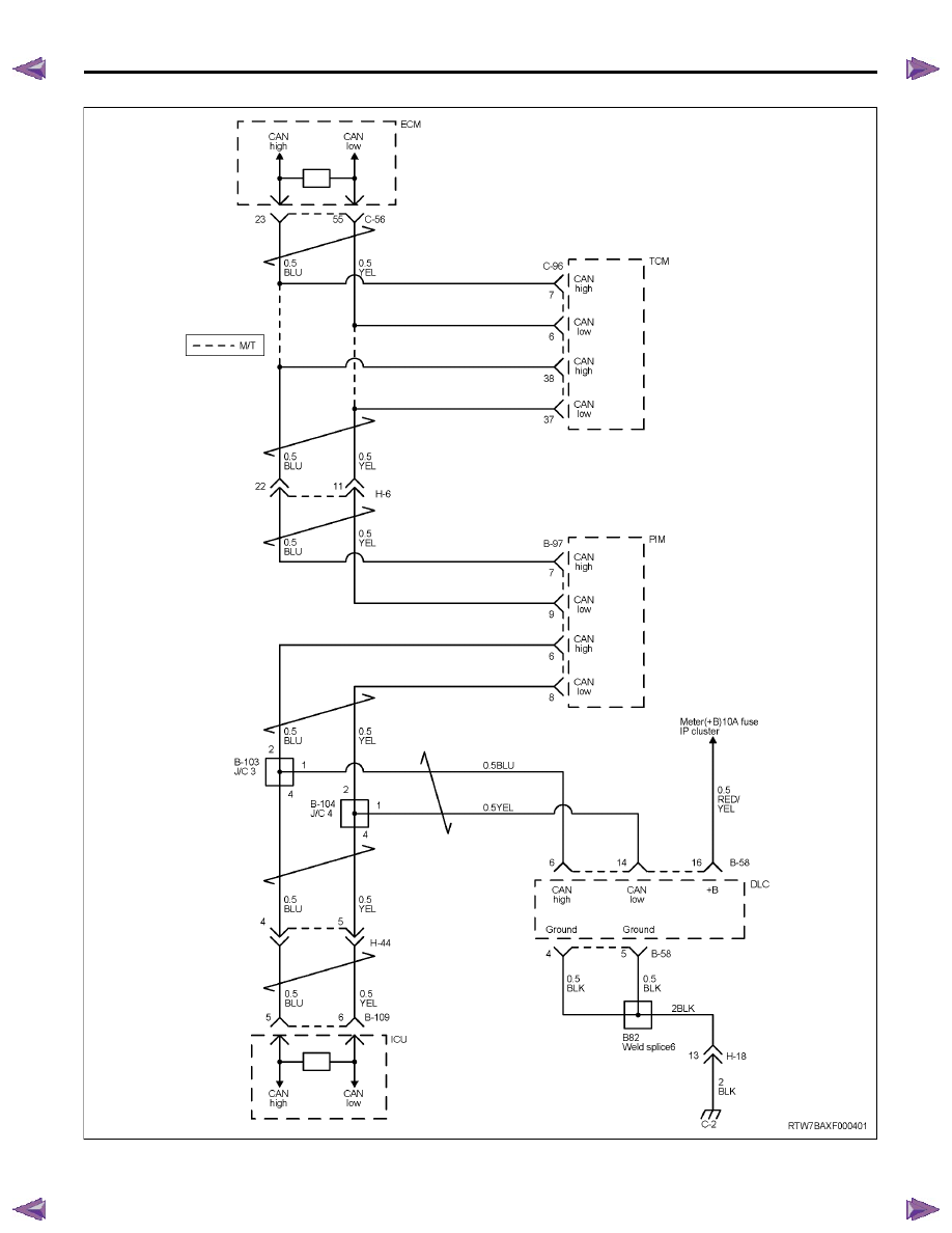
IMMOBILIZER CONTROL SYSTEM (4JK1/4JJ1/HFV6)   11A-5

ICU Communication (HFV6)

11A-6   IMMOBILIZER CONTROL SYSTEM (4JK1/4JJ1/HFV6)

Component Locator

Immobilizer Controls Component View

Immobilizer Controls unit (ICU)

Legend

1. Immobilizer controls unit (ICU)


Engine Control Module (ECM)

Legend

1. Engine control module (ECM) (4JK1/ 4JJ1)

2. Engine control module (ECM) (HFV6)


RTW7BAMF000101

1

IMMOBILIZER CONTROL SYSTEM (4JK1/4JJ1/HFV6)   11A-7

Powertrain Interface Module (PIM)

Legend

1. Powertrain interface module (PIM)

Immobilizer Control Unit (ICU) Connector
End View

Connector No.

B-109

Connector Color

White

Test Adapter No.

J-35616-64A

Pin No.

Wire Color

Pin Function

1

RED/YEL

Battery voltage

2

-

Not  used

3

BLK

Ground

4

-

Not  used

5

BLU

CAN high

6

YEL

CAN low

7

-

Not  used

8

VIO

Alarm cancel (disarm) signal 
output (with anti-theft system)

9

YEL

Ignition voltage

10

-

Not used

11

-

Not used

12

-

Not used

RTW7BASH000501

1 2 3 4 5 6
7 8 9 10 11 12

11A-8   IMMOBILIZER CONTROL SYSTEM (4JK1/4JJ1/HFV6)

Diagnostic Information and Procedures

Diagnostic Starting Point - Immobilizer
Controls

Begin the system diagnosis with Diagnostic System
Check - Immobilizer Controls.  The Diagnostic System
Check - Immobilizer Controls will provide the following
information:

• The identification of the control modules which

command the system.

• The ability of the control modules to communicate

through the serial data circuit.

• The identification of any stored diagnostic trouble

codes (DTCs) and the their statuses.

The use of the Diagnostic System Check - Immobilizer
Controls will identify the correct procedure for
diagnosing the system and where the procedure is
located.

Diagnostic System Check - Immobilizer
Controls 

Description

The Diagnostic System Check - Immobilizer Controls is
an organized approach to identifying a condition that is
created by a malfunction in the electronic immobilizer
control system. The Diagnostic System Check must be
the starting point for any immobilizer system concern.
The Diagnostic System Check directs the service
technician to the next logical step in order to diagnose
the concern. Understanding and correctly using the
diagnostic table reduces diagnostic time, and prevents
the replacement of good parts.

Test Description

The numbers below refer to the step numbers on the
diagnostic table.
2. Lack of communication may be because of a partial
or a total malfunction of the serial data circuit.
6. The presence of DTCs which begin with U, indicate
that some other module is not communicating. 
9. If there are other modules with DTCs set, refer to the
DTC list. The DTC list directs you to the appropriate
diagnostic procedure.

Important:

• DO NOT perform this diagnostic if there is not an

immobilizer system concern, unless another
procedure directs you to this diagnostic.

• Before you proceed with diagnosis, search for

applicable service bulletins.

• Unless a diagnostic procedure instructs you, DO

NOT clear the DTCs.

• Ensure the battery has a full charge.

• Ensure the battery cables (+) (-) are clean and

tight.

• Ensure the ICU ground is clean, tight, and in the

correct location.

• Ensure the ICU harness connector is clean and

correctly connected.

• Ensure the ICU terminals are clean and correctly

mating.

• Ensure the immobilizer security information is

correctly programmed into the ICU, ECM and PIM.

• Ensure the ICU is correctly installed to the steering

lock.

• Ensure objects does not block transponder key in

the steering lock.

• Ensure another transponder key is not attached to

the key ring.

Diagnostic System Check - Immobilizer Controls 

Step

Action

Value(s)

Yes

No

1

Install a scan tool.

Does the scan tool turn ON?

Go to Step 2

Go to Scan Tool 

Does Not Power Up

2

1.

Turn ON the ignition, with the engine OFF.

2.

Attempt to establish communication with the
listed control modules.

• ICU

• Engine control module (ECM)

• Powertrain interface module (PIM)

• Transmission control module (TCM)

(AISIN A/T or 4L-60E)

Does the scan tool communicate with all the listed
control modules?

Go to Step 3

Go to Scan Tool 

Does Not 

Communicate with 

CAN Device


Content   ..  1462  1463  1464  1465   ..