Content .. 1436 1437 1438 1439 ..
Isuzu KB P190. Manual - part 1438
9A1-70 RESTRAINT CONTROL SYSTEM
Step Action
Yes
No
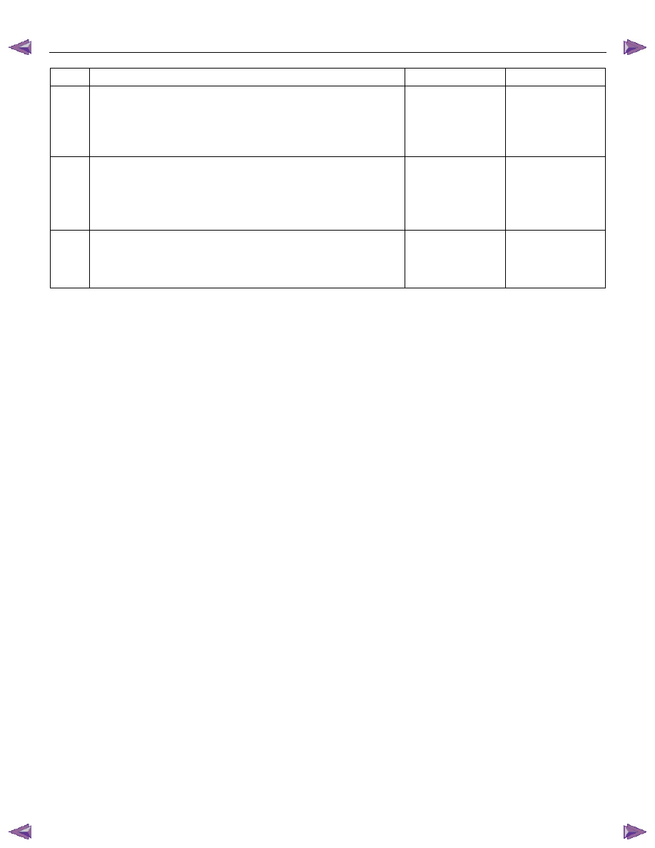
8
1. Ignition switch is at “LOCK”.
2. Measure the resistance from the instrument meter cluster
harness connector "SRS" warning lamp circuit terminal to the
SRS control unit harness connector terminal “4”.
Is the resistance 5.0 ohms or less?
Go to Step 9
Replace the SRS
harness.
Go to Step 10
9
1. Disconnect the instrument meter cluster harness connector.
2. Measure the resistance from the "METER" fuse to the
instrument meter cluster harness connector "SRS" warning
lamp power supply circuit terminal.
Is the resistance 5.0 ohms or less?
Service instrument
meter cluster.
Install instrument
meter cluster.
Go to Step 10
Replace the "SRS"
warning lamp
power supply
circuit harness.
Go to Step 10
10
1. Reconnect all components and ensure all components are
properly mounted.
2. Clear the diagnostic trouble codes.
Is this step finished?
Go to the “SRS
Diagnostic System
Check”
―