Isuzu KB P190. Manual - part 1400


  Index      Isuzu     Isuzu KB P190 - service repair manual 2007 year


Search            


Content   ..  1398  1399  1400  1401   ..


Isuzu KB P190. Manual - part 1400


Cruise Control – HFV6 

Page 8C–22 

 3.3  Stop Lamp Switch Assembly 
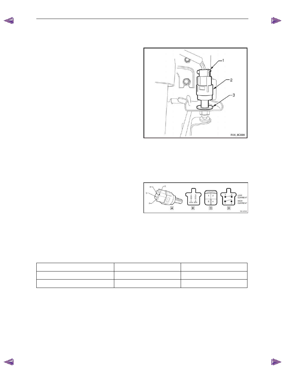
Remove 

Press the connector locking tab while pulling on the 
stop lamp connector (1) and remove from the switch 
assembly (2). 

Twist the stop lamp switch assembly (2) anticlockwise 
a quarter of a turn and pull out of the brake pedal 
support bracket. 

If required, remove the plastic clip (3) by pressing the 
locking tabs on the rear of the clip and pulling from the 
brake pedal support bracket.  

Figure 8C –  10 


Test 

Terminal Testing 

Using a multimeter, probe the pins of the switch 
assembly and compare to the table below. 

N O T E  

The pins are as follows: 

•  C44 – pins 1 and 2  

•  C44 – pins 3 and 4  

N O T E  

Holding the plunger (5) with tape will help when 
performing the test with the plunger in the active 
position (plunger pressed). 


Figure 8C –  11 

Plunger Position 

Connector C44 – 1 and 2 

Connector C44 – 3 and 4 

Neutral position (plunger extended) 

Open circuit 

Continuity 

Active position (plunger pressed) 

Continuity 

Open circuit 


Reinstall 

If removed, install the plastic clip (2) with the arrow pointing upwards, refer to Figure 8C –  11. 

With the connectors pointing upwards (12 o’clock position), insert the switch assembly (1) into the plastic clip. 

Ensure the brake pedal is in the rest position. 

Cruise Control – HFV6 

Page 8C–23 

Push the switch assembly (1) so the plunger is 
pressed and the end switch barrel is against the brake 
pedal (2). 

Twist the switch assembly clockwise to lock into place. 
The distance between the brake pedal and the switch 
barrel should be 0.7 ± 0.5 mm. 

Install the wiring connector to the switch assembly. 


Figure 8C –  12 


Cruise Control – HFV6 

Page 8C–24 

3.4 

Clutch Pedal Switch (Manual Only) 

Remove 

Disconnect the electrical connector (1) from the clutch 
switch (2). 

Loosen the lock nut (3) and remove the clutch switch 
from the pedal bracket. 


Figure 8C –  13 


Test 

Using a multimeter set to measure ohms, probe the 
pins (1) of the switch assembly. 

In the neutral position (plunger extended) there should 
be an open circuit across the switch. 

In the active position (plunger extended) there should 
be a closed circuit across the switch. 

Replace the switch as per the following reinstall 
procedure if the tests prove the switch to be faulty. 

If the test proves the switch to be serviceable, 
reinstall it as per the following procedure. 

Figure 8C –  14 

Cruise Control – HFV6 

Page 8C–25 


Reinstall 

Install the clutch switch (1) as follows: 

Insert the switch into the clutch pedal bracket. 

Rotate the switch clockwise until obtaining the 
clearance (2) between the pedal (3) and the 
pedal stoper. 

Clutch pedal and pedal stoper 
clearance specification............................... 0.5 – 1.5 mm 

Tighten the lock nut (4) to the correct torque 
specification. 

Clutch switch lock nut 
torque specification ............................................31.0 Nm 

Recheck the clutch switch clearance, readjust 
clearance if required. 

N O T E  

No adjustment is required for the clutch switch 
itself. 


Figure 8C –  15 


Reconnect the electrical connector to the clutch switch. 

Verify the operation of the clutch switch by operating the cruise control and checking the clutch switch stops 
operation of the cruise control when the clutch pedal is pressed. 


Content   ..  1398  1399  1400  1401   ..